0 to 20 Volt, 20 Ampere DC Bench Power Supply

cathead

CATWERKS LTD
Registered
Joined
Feb 7, 2013
Messages
2,487
The cold days of winter are good for an electronic project or two so decided to build up a power supply for the electronics bench.
An old uninteruptable power supply case served well for the project's cabinet as well as a heavy 120/15 volt AC transformer.
I used an LM317 voltage regulator and 4 2N3771 NPN power transistors in my design and added meters for both voltage and
current. I used Ohm's Law to determine the series resistance for the volt meter and parallel resistance for the ammeter and
tested the meters against my trusty old Simpson 260 VOM. It's great to have something to power testing radios or other
electronic equipment, charge batteries or just have power for a bit of experimentingP1030427.JPG.
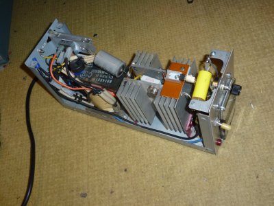
I was lucky to have two large heat sinks in my box of junk as the mounting of the power transistors was relatively easy that way. I could add a fan
if it proves to be necessary and the heat sinks get too hot with a heavy current draw.
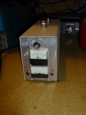
P1030430.JPG
The potentiometer allows one to select the voltage needed for the application. I used some banana plug
sockets so I can use the test leads from a VOM or make up some heavier ones if needed. My total
investment is less than $20 and that was for the voltage regulator and power transistors. Everything
else was stuff I had on hand in my boxes of electronic junk. The project did get me into the shop for
several hours to drill some large holes for the meters and get them mounted on an aluminum plate.
 
Nice job! It is always fun when you can combine skills to make something useful.
 
Nice job, Cathead!

The LM317 and its larger brother, the LM350, have been my go-to voltage regulators for decades. You might want to post the schematic for those interested.

A question; the filter capacitor(s) don't look very large for a 20 amp supply. Have you noticed any voltage droop at 20 amps output? As I recall, the LM317 is good for 37 volts max on the input which would be 25 volts rms. At 37 volts peak and full wave rectification, my calculations indicate that a 11,000 mfd filter capacitor would be required to supply 20 volts at 20 amps without the regulator dropping out.

An interesting use for the LM317 is as a constant current regulator. It regulate the throughput resistance so that the output pin is always 1.25 volts above the adjust pin. If a low resistance is placed between the output pin and the adjust pin and the output is taken from the adjust pin, the output current will be regulated at 1.25x the resistance. I used that fact to make a 25 amp constant current supply for anodizing. For higher current, it isn't feasible to use a variable resistance but there is a more complicated circuit which permits a higher resistance potentiometer. That circuit was found in the National Semiconductor data sheet's application notes.
 
Something to add is current limiting.

When working in equipment a current limit reduces damage from mistakes.


Sent from my SM-G781V using Tapatalk
 
Nice job, Cathead!

The LM317 and its larger brother, the LM350, have been my go-to voltage regulators for decades. You might want to post the schematic for those interested.

A question; the filter capacitor(s) don't look very large for a 20 amp supply. Have you noticed any voltage droop at 20 amps output? As I recall, the LM317 is good for 37 volts max on the input which would be 25 volts rms. At 37 volts peak and full wave rectification, my calculations indicate that a 11,000 mfd filter capacitor would be required to supply 20 volts at 20 amps without the regulator dropping out.

An interesting use for the LM317 is as a constant current regulator. It regulate the throughput resistance so that the output pin is always 1.25 volts above the adjust pin. If a low resistance is placed between the output pin and the adjust pin and the output is taken from the adjust pin, the output current will be regulated at 1.25x the resistance. I used that fact to make a 25 amp constant current supply for anodizing. For higher current, it isn't feasible to use a variable resistance but there is a more complicated circuit which permits a higher resistance potentiometer. That circuit was found in the National Semiconductor data sheet's application notes.

Yes, some more filter capacitors may be needed. I havn't tried any big current draws yet so don't quite know what to expect. One of
the circuit diagrams I looked at had four 4200 microfarad capacitors in parallel for a 20 ampere supply. I will have to look around
and see if I can round up some bigger electrolytics. I used the "cookbook" method of wiring up the circuit by looking at a few
diagrams of the general idea of what I wanted and then just went from there. I do the same thing in the kitchen by looking at a few
recipes to get the general idea of the ingredients. I do have more capacitors but they are for mounting on printed circuit boards and would
prefer some with axial leads.
 
Something to add is current limiting.

When working in equipment a current limit reduces damage from mistakes.


Sent from my SM-G781V using Tapatalk

I will look into that. Maybe a SCR/and zener diode would be the ticket...
 
I have it's brother by a different mother.
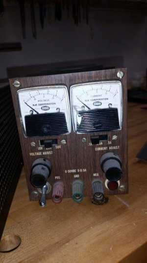
Mine was made long, long ago here in NJ... constant voltage, constant current.
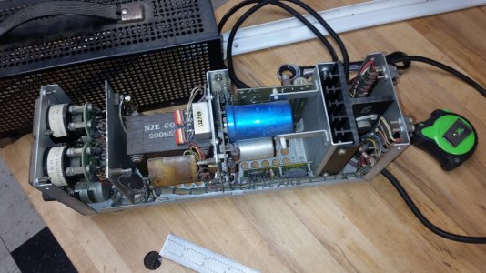
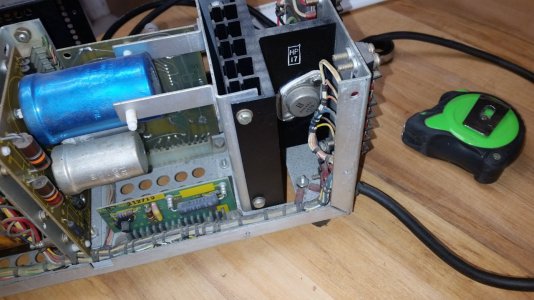
I have to fix it. I put a multi meter on the back panel and blew it up. My neighbor thinks I blew the transistor. I just wanted to know what all the connectors were doing. Been sitting dead for about 5 years now... maybe its time to resurrect it.
20220127_220006.jpg20220127_220012.jpg20220127_220026.jpg
 
That is a nice looking unit. I admire that you actually did the math and designed and built it.

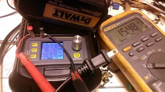
I cheated on my DIY CC/CV supply and used chinese DC/DC buck/boost modules off ebay. It's only 0-20V & 0-2A but it runs off of a Dewalt cordless tool battery so I call it a "field supply" as opposed to a "bench supply." It's embedded in an old Dewalt charger (still works to charge the battery).

dewalt PS.jpg

18-20V from the battery goes through a low voltage cutout circuit I rolled, and from there into a boost module to pump it up to 24VDC which is exposed via binding post jacks on the opposite side of the charger for powering 24V devices and sensors. From there 24V goes to the 0-20V cc/cv buck module. On the side in the picture you can see 2 more binding post jacks, that's where you get the CC/CV power.

One pitfall of it, the undervoltage cutout is defeated if you use it while the charger is plugged in, and the device under test draws more than the charging current. I killed a battery once by leaving it plugged in over a weekend while powering a touchscreen HMI.

link to build thread
 
I would definitely consider forced air over those heatsinks. If you are set to provide 5 volts at 20 amps, then the power transistors are dissipating OVER 300 watts across them. That is a LOT of heat for passive heatsinks to get rid of. The closer you are operating to your maximum of 20 volts, the less heat you will have to dissipate.

Otherwise, it looks like a solid classical design. I would suggest moving your LM317T to a different location, where it does not block the top of the heatsink, and also provide less cooling for the regulator. As with any power supply, make sure your fuse is easily replaceable and does not have to be unsoldered to be replaced.
 
Back
Top