Achieving reproducibility

This post is a question about how to achieve repeatability--making several parts fit the same blueprint.

But first some background::

I am building several telescopes from 13" to 20" to 30" diameter apertures. I bought my milling machine and lathe in order to be able to hit better accuracies, I also bought some dial indicators, calipers, a set of micrometers, and a few other things of metrology. In many respects, I am doing "all right" and in a few I keep running into the "how did that happen" category. All of the machined material in this post is 6061T6 of extruded bar stock.

The 13" mirror cell has 6-points that through the back side of the mirror. These 6 points are on 3 balance beams. In rough numbers the beams are 4.2" long, 0.600" wide, and 0.500" tall. I can routinely rough 3/4*3/4 stock into the required dimensions within 0.0015" measured at 9 places around the parts and have 3 parts that are all within 0.0005 to 0.0015 of each other. All well and good.

At both ends of the beam I drill (0.4375) trying to get both holes exactly 3.902" apart (or as close as I can make them). After drilling and without moving the part, I switch from drilling to the boring head and bore the hole to 0.468 which is a "bearing fit" to the 12mm ball transfers that touch the back side of the mirror at very low friction levels. I start with beams that are long enough that the accuracy of the holes on (say) the left end of the beam are not critical as long as these holes are the same away from that end of the beam. When the part goes into the vise, it is supported on parallels and another parallel is clamped to the vise so that the left edge of the part can be positioned easily. The bored holes have been measured with a snap gauge and the micrometers and I am seeing a similar 0.0015"-0.002" variation in the bearing fits of these holes.

After drilling and boring all three beams, I position the table so that it has moved 3.902". I confirm this by making the first hole in a sacrificial material and measure the near sides and far sides of said hole, the average of which is the center to center distances. These are all measured with a dial caliper. I then clamp down the table, insert each part, drill and bore each part. After wards, I measure the overhang off the ends of the part and edge mill the beams to final length centered around the bored holes.

At this point I have 3 parts: one with 3.9025" hole spacing, one with 3.9015" hole spacing, and one with 3.899" hole spacing. While this is better than is probably needed for the project at hand, If anyone can help me locate the point at which I lead error creep into the machine process I would be appreciative.

After milling the beams to length such that the material from the far end of the hole to the edge of the beam is "the same" (about 0.016" as accurately as I can measure it), I use the beam length to find the center of the beam and drill an axial hole perpendicularly through the beam. I proceed to drill a hole using a C drill (0.242") backed up with a D drill to 0.110 depth. This D drill is a nice thumb bearing fit to the miniature ball bearings (1/4×1/8×7/64) that are needed on this balance beam. The problem, here, is that the drilled hole walks about 0.002" while passing through the beam. This puts the axis off center of the beam, and makes balancing the beam in 2 dimensions extraordinarily hard. Here the question is how does one get holes on one side of a part to match up to a hole on the other side of the part to (say) 1/2 a thou? at these tiny dimensions? how does one bore a bearing fit at this kind of dimension (I don't know where to get the tooling to do bores at this size)?

The numbers above are after making this set of beams 3 times and learning the more obvious mistakes of part positioning and tolerance stackups. As I said, the current parts are usable, but future machine parts will not be so tolerant of litter errors of part position prior to machining.

Thanks in advance.
I think if you are going to make a number of these parts you should look into making or have someone make you a drill fixture. With a fixture you don’t need to rely on table movement. The fixtures have hardened drill bushings that once made stay the same.
Jimsehr
 
I just want to go back to your dials & lead screw. I think you are saying you don't have a DRO but validated the X displacement dial graduations against an indicator & its sufficiently accurate. So when you are going to your hole positions you use the crank/graduations, ie. you don't have an indicator set up to independently show displacement, right?

If so, I see one more potential error source. When you lock the tables on these typical Asian machines its incredibly easy to displace it because of the cheesy way the lock screws act against the gib strip. It imparts a small tourque & can easily move the table behind the scenes & your dial is not the wiser. I'm not saying your mill is exactly like mine but maybe test this. I had the exact same issue on my lathe. It was actually the DRO installation that flagged this. I would set the position to 1.000", lock the table and it easily move to 0.998" to 1.002" as evidenced by the DRO.

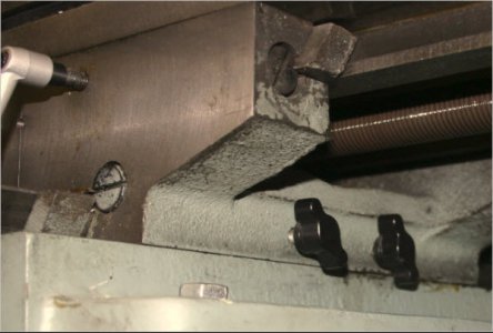
This is an old pic before the mod, but I replaced these plastic knobbed screws with a modified bolt that has a bearing ball affixed to the end. It imparts force to a little brass shoe that is like a cylinder with its end chamfered to match the dovetail. So it slow friction & nil torque imparted to the shoe which clamps linearly against the gib strip. Now I get virtually zero table movement when I lock it down. (ps - a DRO is a great investment!)

SNAG-11-24-2017 0001.jpg
 
Last edited:
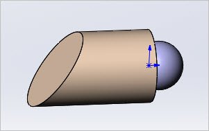
This is what I made for my lathe (same tightening displacement problem & similar principle). I just inserted it into the set screw hole. The screw itself was countersunk to kind of cup the ball. Note, you have to have a way to remove this in the case of a blind hole, either by moving the table to expose it or chewing gum on a stick etc :)

SNAG-11-24-2017 0002.jpg
 
Mitch,
I've never seen an indicator with graduations that include "spot on".
I don't know what "spot on" means relative to deviation over distance nor even the resolution of the indicator.
When we're trying to converge on tolerances in the "tenths", via the internet, sharing a common understanding of the details is critical, IMO. When I read others using adjectives rather than units of measure to describe something (precision?) I can only infer that it's 'good enough' for the author.

You're getting lots of good advice here and I don't think I can help anymore.

To satisfy my curiosity please reply: You said you used a snap gage and micrometers to measure the bored holes. I think you mean telescoping gage, not snap gage. Correct? Post a picture?
 
I just want to go back to your dials & lead screw. I think you are saying you don't have a DRO but validated the X displacement dial graduations against an indicator & its sufficiently accurate. So when you are going to your hole positions you use the crank/graduations, ie. you don't have an indicator set up to independently show displacement, right?

If so, I see one more potential error source. When you lock the tables on these typical Asian machines its incredibly easy to displace it because of the cheesy way the lock screws act against the gib strip. It imparts a small tourque & can easily move the table behind the scenes & your dial is not the wiser. I'm not saying your mill is exactly like mine but maybe test this. I had the exact same issue on my lathe. It was actually the DRO installation that flagged this. I would set the position to 1.000", lock the table and it easily move to 0.998" to 1.002" as evidenced by the DRO.

This is an old pic before the mod, but I replaced these plastic knobbed screws with a modified bolt that has a bearing ball affixed to the end. It imparts force to a little brass shoe that is like a cylinder with its end chamfered to match the dovetail. So it slow friction & nil torque imparted to the shoe which clamps linearly against the gib strip. Now I get virtually zero table movement when I lock it down. (ps - a DRO is a great investment!)

I validated the long and short horizontal axes with a DI on a magnetic base measuring the position of the quill (several times.)
The long axis has its dial exactly match the DI (1.000 on the dial == 1.000 on the DI) after 1 inch of travel with DI at 1.000. move DI and reset it to 0.000 then move axis again.
The short axis has its dial read 1.000 when the DI reads 0.9997 EDIT:: make that 0.997 not 0.9997, and this repeats as the DI is repositioned.

I will have to watch the table as the locks are applied. However in the case of these 3 balance beams, the table remained locked for the machining of all three beams.

I may have to do a ball bearing trick too.

Thanks.

Mitch,
I've never seen an indicator with graduations that include "spot on".
I don't know what "spot on" means relative to deviation over distance nor even the resolution of the indicator.
<snip>

To satisfy my curiosity please reply: You said you used a snap gage and micrometers to measure the bored holes. I think you mean telescoping gage, not snap gage. Correct? Post a picture?

Spot on means the reading on the dials are exactly the same reading as on the dial indicator.
I did mean telescoping gauge (I had heard they were also/sometimes called snap gauges) In any event, the box they came in says telescoping gauges.
 
Last edited:
I think you may have a number of factors at play here. When holding this type of tolerance lots of little things can have an effect. Making sure any backlash in the screws is taken out before moving the table, runout in a drill chuck, having one lip a bit long or the angle a bit off on the drill, just to name a few. As far as boring small holes goes you just need a tiny boring head and a tool ground, (or purchased) that is small enough to do the size your trying to do. Micro 100 makes a whole series of small boring bars for just this purpose.

I could tell you how I would do this, but it would be pages of written procedure. If you lived near me Id be glad to have you over and help you work this out. Want a trip to the cold, snow and ice?

Doing this level of work requires adherence to procedure, a good set up, sharp tools. Repeatability requires doing the correct procedure the same way multiple times. This is what separates the men from the boys as the saying goes. Im not sure if you watch any of the YouTube machinist creators but, looking at the process and time spent doing set up by guys like Tom Lipton (OxTools),Robin Rinzetti and Stefan Gotteswinter you will get what Im talking about. Having the tools is a great first step, having the experience.... well it takes experience.

This is not easy, look at the results you give us above, your doing well! Keep at it and you will get it.
 
I could tell you how I would do this, but it would be pages of written procedure. If you lived near me Id be glad to have you over and help you work this out. Want a trip to the cold, snow and ice?

maybe in the summertime......

Doing this level of work requires adherence to procedure, a good set up, sharp tools. Repeatability requires doing the correct procedure the same way multiple times.

I have literally watched hundreds of hours of Lipton, Abom79, Fenner, Doubleboost, .....
I think the problem described above is one that an experienced machinist could see in a few minutes of watching my work habits, procedures, setups, and measurements.

This is what separates the men from the boys as the saying goes. Im not sure if you watch any of the YouTube machinist creators but, looking at the process and time spent doing set up by guys like Tom Lipton (OxTools),Robin Rinzetti and Stefan Gotteswinter you will get what Im talking about. Having the tools is a great first step, having the experience.... well it takes experience.

This is not easy, look at the results you give us above, your doing well! Keep at it and you will get it.

I have no choice but to continue, the mirrors for the scopes are already in hand.
 
Sounds like some good advise, I might add some may be to backlash , the take up backlash may in fact only be when it's locked down.
 
I might add some may be to backlash , the take up backlash may in fact only be when it's locked down.

I "take out the backlash" by using several means::
a) move the table in only 1 direction after finding an edge
b) setup a DI when the distance table moves is small (taking backlash out of the equation)
c) move the table 40/thou the other direction before moving it forward.

As to a): When I use an edge finder, I move the part up towards the spinning edge finder, watch the finder become cylindrical, then watch for the kick. With my edge finder, I can set the dial to 0.000, back the part away 40/thou, come back, see the kick, and be within 1.5/thou on the dial. I'm not really happy with this lack of precision/accuracy, but this is what I can do right now.

As to c): the dial movements of backlash are on the order of 10-12/thou, moving the table 40/thou means the grease will have moved in the position bearings and hopefully eliminate squishy "readings".

I think I have a number of small issues; all adding up to give me the errors reported above.

Thanks again.
 
I’m going to simplify your process to keep from being wordy. If I understand correctly you have some type of fixture and prep the pieces and bore one end of the beams. Then you step off the center distance and verify, lock everything down and proceed to bore the opposite end. In essence all three beams have been removed and reinserted into the fixture. If this is the case a .003 variation is pretty good, in the shops I worked in would not use that procedure unless we had at least a +/- .01” tolerance. The center drill and drilling process should have nothing to do with the error as the boring should take care of any discrepancies.
If this is not the case disregard my ignorance.
If it is the case and I needed tighter tolerances I would proceed like you did in the first phase. When boring the opposite end I would use your system that verified the center distance on each beam eliminating most errors except that of measuring.
You can have fast or accurate but rarely can you have both at the same time.
 
Back
Top