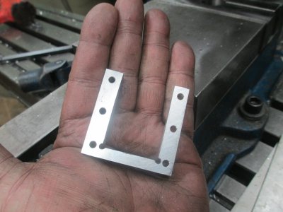
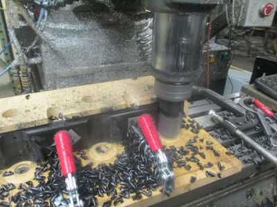
Another example of a multi-step machining operation. The goal of this thread is to show the thought process that goes into making the part while minimizing any errors that can creep into the process, as well as a proceeding in a logical order of operation to minimize setup and tool changes.
I am helping another member, Alloy, retrofit his Shizouka AN-S CNC mill
http://www.hobby-machinist.com/threads/shizouka-an-s-build.33868/
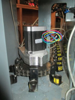
For system compatibility and ease of control we decided to power the tool changer with a stepper motor rather than the Geneva drive system that it had originally. I designed a 16:1, double reduction, inline gearbox that will fit in almost the same footprint as the original system.
The concept:
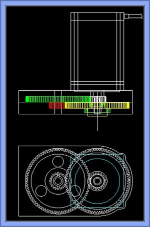
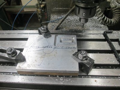
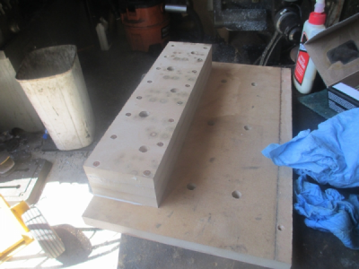
The layout for machining operations. The material is a chunk of 6061 aluminum 19 x 6 x 0.75 .
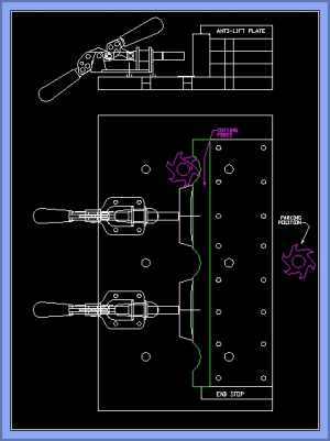
Turns out I only needed about 17 inches. The part drawing is overlaid on a drawing of my mill table so I can get the bolt hole layout to align with the T-slots.
Since I do most of my machining in the lower left quadrant ( -X, -Y) ( it's a long story), 0,0 is at the upper right corner of the work. The dimensions are to 4 decimal places on the drawing only because this is what I have the CAD program set to, the actual positioning on the table is done with a tape measure and a scale. Not terribly accurate, nor does it need to be for this part of the process.
This drawing shows the upper and lower gear case halves laid out on the work piece. The dimensions on the drawing are to position the work on the table, and to pre-stage the t-nuts under the work. I won't be able to get to some of them once the work is bolted to the table.

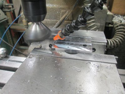
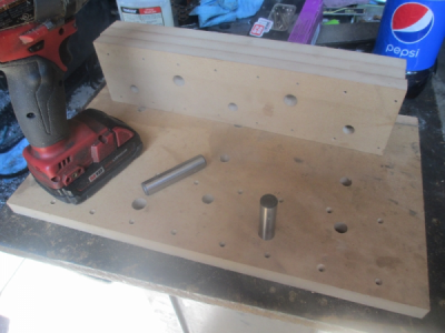
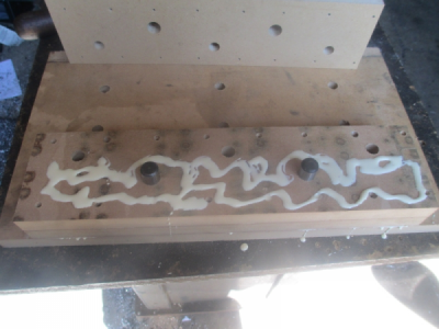
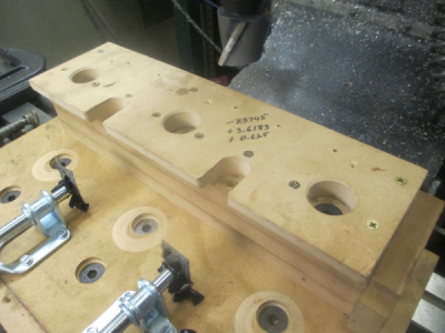
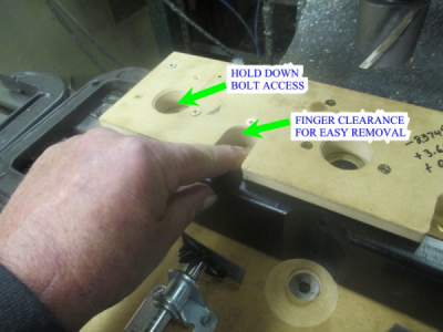
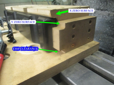
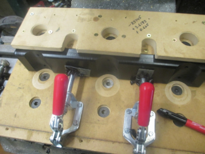
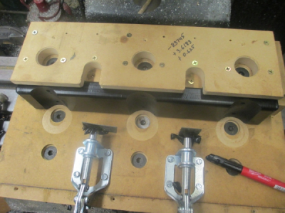
First the spindle is set to the center of the middle T-slot, Y = -3.000 in this case, working 0,0 will be set after the work is bolted to the table. The work is positioned and clamped to the table with normal clamps until the bolt holes are drilled. X zero is set once the work is clamped down. This allows the bolt holes to be drilled through the work and the 3/4 inch MDF backer board. Then go back and C-sink the bolt holes for 1/2'', flat head cap screws, C-sink deep enough that the screw heads won't be hit during the facing operation. The Sharpie marks on the table are where the T-nuts are positioned under the work. Once the work is bolted down and the clamps are removed, then the working 0,0 is reset at the upper right corner of the work. This position will not change for the duration of the process.
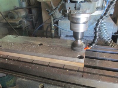
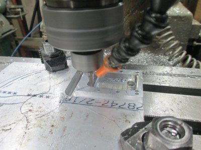
Once the working surface is flat, then time to drill (and tap as needed) all of the holes needed. First center drill all of the holes, then go back and I'm working with a CNC machine here, but everything I am doing also applies to a manual machine except that the process and part would change just a bit and I would make use of a boring head quite a bit more. With a manual machine I would also just round off the end on a rotary table as the last step in the process, rather than profiling it as I did here, but the rest of the process would remain pretty much the same. The outside profile is not a critical dimension so anything close is fine. The critical dimensions here are the bearing bores, and the axial spacing for the gears.
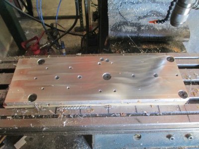
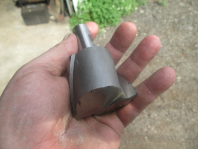
Once the holes were drilled, now is time to change over to the 1/2 finishing rougher end mill (now there's an oxymoron)
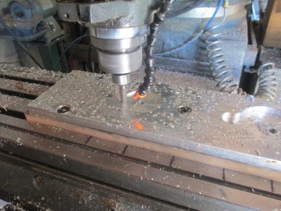
The internal gear housings have been pocketed, and the lower output bearing bore was done with the boring head. Then work was bolted down through the axial holes to the pre-staged T-nuts. The work was never free on the table, the flat head cap screws were then removed for the next operation.
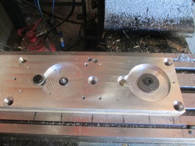
The rough outside profile is complete, about 0.050 oversize. All of the internal work has been done on both of the gear housings, except the 7/16 axle hole, this will be the last operation.
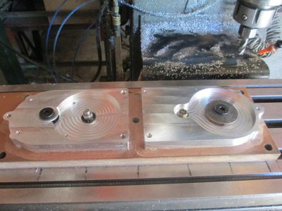
Once rough profile was done, then I removed the upper gear case from the table and flipped it over onto the bottom gear case. I used some flat head screws to align the two parts and hold them together while drilled and reamed the dowel pin holes. Now these parts are married and can't move. Then I went back and C-bored for the socked head cap screws and bolted the halves together. At this point I still have not un-bolted the lower gear case from the table so zero position has not changed.
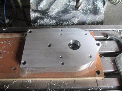
Now it's time to cut the motor aligning pocket. Because I have not moved the lower gear case, this pocket will be aligned with the output bearing bore. The center hole there is just clearance, not a critical dimension. The motor pocket is a critical dimension, and it is 0.001 larger than the flange on the motor.
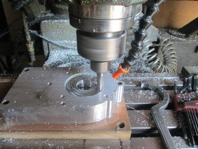
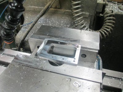
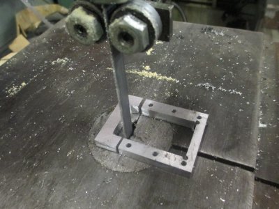
Finish profiling the work, because the parts are bolted and dowel pinned, it will look like it was supposed to be, rather than just happening that way.
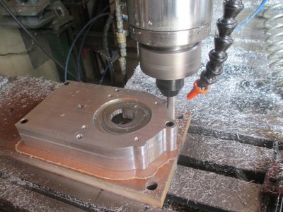
There is still one operation left, and that is the axle hole for the intermediate gear set, that is the 3/8 hole in just to left of center.
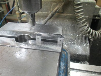
I was my intention to drill and ream to 7/16, but I found that the drill bit had walked a bit and the hole was about 0.005 off of where I wanted it. I tried to find an under size 7/16 end mill in my stash, but no luck. I would have used a boring head to re-locate the center on a manual machine, but in this case it was just as easy to pocket the hole. Once that was complete, I unbolted the top gear case, and need to pocket the axle hole in the bottom gear case. Only the 3/8 bolt was removed after the clamp was installed on the back, using one of the pre-staged T-nuts.
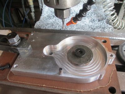
The operations on the gear case are complete, now I can unbolt the lower gear case from the table.
The parts. There is still some work to be done on the gears.
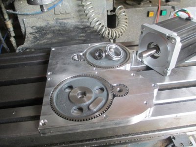
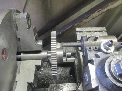
The output gear rides in a bearing in the lower gear case so the hub had the be turned to fit. The bore from the factory is concentric with the OD of the gear, so I turned and threaded a stub arbor to hold the gear while turning the hub OD. I didn't have a tool in a holder that I could reach past the OD of the gear with, so I just grabbed a boring bar that was already in a holder to turn the OD. I just turned the spindle in reverse for this operation.
Kind of an exploded view of the setup.
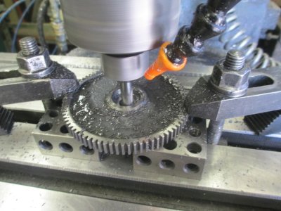
Pocketing the other side of the gear for the lower motor shaft bearing, This gear will be turning at 1/16 the RPM of the motor shaft. Setting up the bearings like this insures things won't walk around inside the gear case.
I again centered up on the bore, and completed the operation. Again, this could have been done with a boring head.
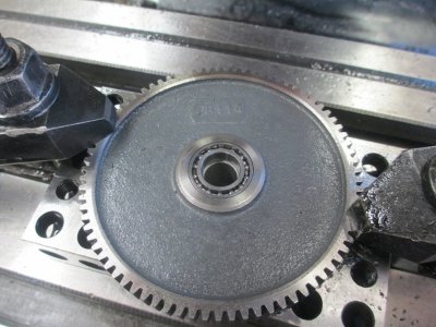
And there it is!
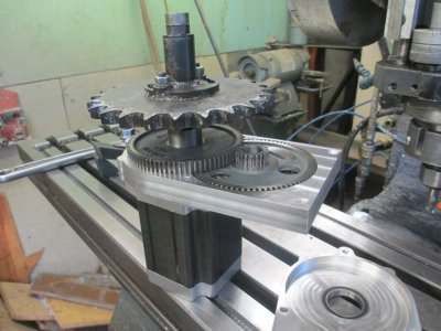
And kind of in place, need to relocate the rear mount a half inch to get every thing to fit and rotate it into position.
