- Joined
- Sep 20, 2019
- Messages
- 1,394
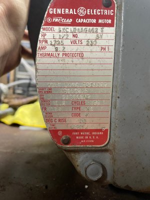
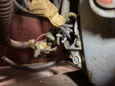
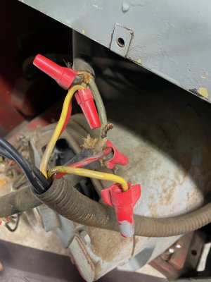
I need help wiring my Colchester Master 6.5 lathe motor. The motor ran fine before diving into this project. I don't know why a previous owner bypassed the main electrical panel, safeties, and reverse switch, but he did. I am hoping that I can understand what connections to make at the motor, and then I will be able to figure out how to incorporate the main panel wiring and reverse switch. The likelihood of it is doubtful, but I'm determined and appreciate your help. The next two pictures are of the motor ID plate and the nasty wiring from a previous owner.
I took the motor apart, cleaned everything, and replaced the bearings today. The start and run caps were fine. The centrifugal switch and thermostat also appear to be fine. After cleanup, I found the printed numbers on the wires, but I don't know how to wire them together.
This is the end bell with the centrifugal switch and thermostat, before cleaning and bearing replacement.
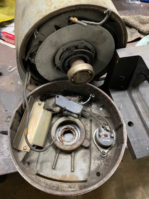
The thermostat has wires 7, 10 & 11. Using my multimeter, 10 and 11 are connected at rest. 7 does not have continuity with 10 or 11, so I assume if the motor overheats, 7 energizes the thermostat, and the 10 & 11 connection is broken. Does this sound about right? I assume 10 & 11 are in line with power in, but I don't know how #7 connects. Then there's the centrifugal switch. It has an unmarked black wire from the start cap to the switch. The #8 wire perhaps is in line with the power wire from the thermostat?
There are 4 wires coming out of the housing from the windings/caps, numbers 1, 4, 5 & 8. I used my multimeter to confirm that #8 goes to the centrifugal switch and #5 goes to the run cap. I didn't find any continuity to or between #1 and #4.
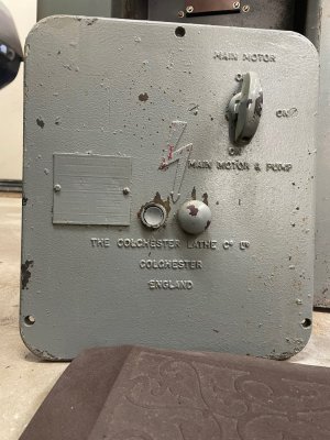
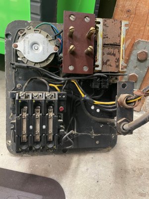
I throw in the control panel and reverse switch, and I don't blame you if you leave this post I'm doing this because the 220V line in will go to the contactor on the control panel. I disassembled everything on the control panel, and cleaned and tested all the switches, etc. All appear functional though I did not apply power to anything. Even the 2 amp Slydlock fuses were good. I polished all the contacts and found nothing obviously wrong. The main switch has Off, On, and On with the coolant pump. I believe the external and recessed momentary switches in the center of the panel for start and stop, respectively.
 And here's the reverse switch
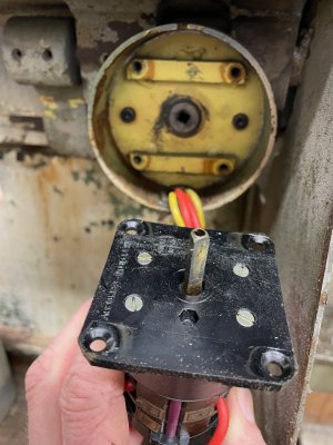
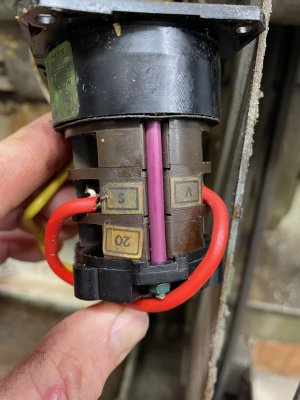
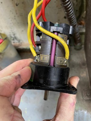
The red and yellow wires from the reverse switch extend to the motor housing but had been bypassed.
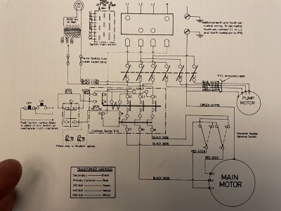
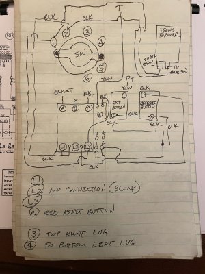
Below is the only wiring diagram in the manual for a single-speed motor. It's 3 PH and mine is single. Otherwise, it looks about the same. Below this picture is my chicken scratch diagram. I was a little paranoid about removing everything and not being able to put it back as it was. Someone had been in here before.
I'm going to keep working through this. I'm not in a big rush as I'm still disassembling the lathe for cleaning and painting. Thanks!


I took the motor apart, cleaned everything, and replaced the bearings today. The start and run caps were fine. The centrifugal switch and thermostat also appear to be fine. After cleanup, I found the printed numbers on the wires, but I don't know how to wire them together.
This is the end bell with the centrifugal switch and thermostat, before cleaning and bearing replacement.

The thermostat has wires 7, 10 & 11. Using my multimeter, 10 and 11 are connected at rest. 7 does not have continuity with 10 or 11, so I assume if the motor overheats, 7 energizes the thermostat, and the 10 & 11 connection is broken. Does this sound about right? I assume 10 & 11 are in line with power in, but I don't know how #7 connects. Then there's the centrifugal switch. It has an unmarked black wire from the start cap to the switch. The #8 wire perhaps is in line with the power wire from the thermostat?
There are 4 wires coming out of the housing from the windings/caps, numbers 1, 4, 5 & 8. I used my multimeter to confirm that #8 goes to the centrifugal switch and #5 goes to the run cap. I didn't find any continuity to or between #1 and #4.
I throw in the control panel and reverse switch, and I don't blame you if you leave this post
 I'm doing this because the 220V line in will go to the contactor on the control panel. I disassembled everything on the control panel, and cleaned and tested all the switches, etc. All appear functional though I did not apply power to anything. Even the 2 amp Slydlock fuses were good. I polished all the contacts and found nothing obviously wrong. The main switch has Off, On, and On with the coolant pump. I believe the external and recessed momentary switches in the center of the panel for start and stop, respectively.
 And here's the reverse switch


The red and yellow wires from the reverse switch extend to the motor housing but had been bypassed.

Below is the only wiring diagram in the manual for a single-speed motor. It's 3 PH and mine is single. Otherwise, it looks about the same. Below this picture is my chicken scratch diagram. I was a little paranoid about removing everything and not being able to put it back as it was. Someone had been in here before.


I'm going to keep working through this. I'm not in a big rush as I'm still disassembling the lathe for cleaning and painting. Thanks!
