- Joined
- Sep 22, 2010
- Messages
- 7,222
[h=1]Wiring a Universal Motor[/h](with thanks to Bill Brown)
The following describes how to deal with an AC/DC "universal" motor that has 4 unmarked wires coming out. Be sure you don't have some other motor, such as a 3-phase unit.
Other motors are covered in an FAQ for the newsgroup rec.woodworking. The FAQ postings (six of them) for rec.woodworking are normally posted around the first of each month, and possibly also posted to the newsgroup news.answers. I can't say how long *your* news system will choose to keep these around! Look for "Frequently Asked Questions about Electric Motors." Also, the "Electrical Wiring FAQ" may be of interest.
The universal motor is called that because it can run on AC or DC. Older units might have been designed this way because very early power distribution had not settled on AC or DC, or with 50 or 60 cycles. Thus, such a motor could be used universally, in all locations provided the voltage was within reason. This still may be a concern with some on-site jobs feeding power tools from DC sources such as portable welding rigs. Another nice thing about these motors is that they are easily reversible. They are also easily speed-controlled, such as in hand drills, whereas induction motors prefer to run at or near synchronous speed.
The first task is to determine which two wires go to the armature, and which go to the field winding. If you can't tell by examining where the wires go (or the nameplate), get an ohmmeter and connect it to the wires until you find two that show some continuity. Rotate the shaft slowly by hand and note if the resistance changes as you turn it. If it does, you probably have the armature, and the fluctuations are due to the brushes making and breaking contact with the commutator. The other winding (field coil) should show a steady resistance.
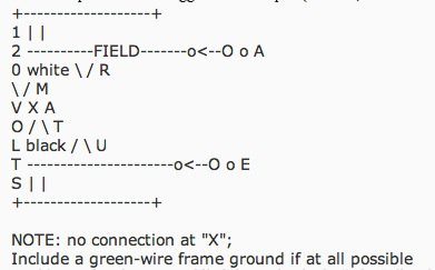
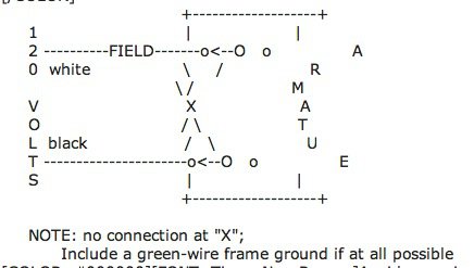
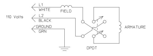
Presuming you want the ability to reverse the motor, find a switch that can handle the rated current, in the double-pole-double-throw configuration with a center-off position. The suggested hook-up is (as usual, a bad ASCII graphic):
+-------------------+
1 | |
2 ----------FIELD-------o<--O o A
0 white \ / R
\ / M
V X A
O / \ T
L black / \ U
T ----------------------o<--O o E
S | |
+-------------------+
NOTE: no connection at "X";
Include a green-wire frame ground if at all possible
Avoid reversing the motor while it is moving in the "other" direction as this could severely stress the switch and motor (particularly the brushes). Move the switch to the center (off) position, and continue on to the other direction after the motor has stopped.
Please, always be careful when dealing with electricity. If you don't feel comfortabl


