Hello all,
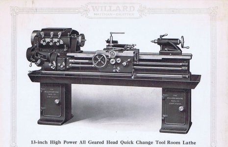
I have been working on and off over the past year fixing up a 1917-ish Willard Machine Tool Co. "13 Inch High Power All Geared Head Quick Change Tool Room Lathe"
http://www.vintagemachinery.org/pubs/4362/17712.pdf
I haven't used the machine much at all yet, I am now making new adjustment screws for the tapered gibs on the cross slide and compound. Earlier today I was using it to drill a 15/32" hole in the end of some rod, at 500 rpm (the machines highest) the clutch was slipping out under the load of the drill. I was also needing to pull up quite hard on the clutch lever to keep it's rpm up. I know it was not the belt from the motor to the clutch pulley slipping.
Am I going to need to open up the clutch to sort this out? Or is it a matter of the machine not being designed to give much torque at it's high-end? I would really love to not take the clutch apart, as to do so I need to remove the clutch by craning off the motor and opening the head and removing an internal jack shaft with idler pulleys. Something I just did and undid a few days ago, thinking it would be the last time for a while When I had the clutch off last I didn't open it up as it looked so clean inside I figured it was fine.
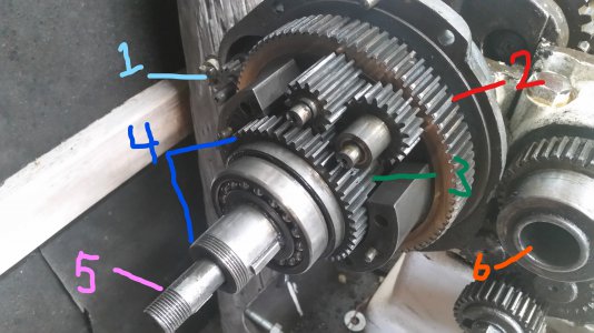
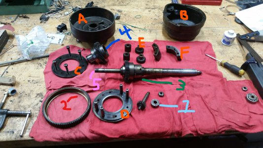
I'm not sure how the clutch operates, but I'm guessing a cone clutch get's pushed into a pulley and turns a shaft via some planetary gearing.
The clutch is where that shiny round pulley is behind the headstock. I have the motor on top of the head. I can take pictures tomorrow if it would help. (As an aside, does anyone know the headstock taper? The linked document says #3 morse, but its way bigger and doesn't feel tapered at all. I'll take some measurements but thought I'd ask while I was at it.)

I have been working on and off over the past year fixing up a 1917-ish Willard Machine Tool Co. "13 Inch High Power All Geared Head Quick Change Tool Room Lathe"
http://www.vintagemachinery.org/pubs/4362/17712.pdf
I haven't used the machine much at all yet, I am now making new adjustment screws for the tapered gibs on the cross slide and compound. Earlier today I was using it to drill a 15/32" hole in the end of some rod, at 500 rpm (the machines highest) the clutch was slipping out under the load of the drill. I was also needing to pull up quite hard on the clutch lever to keep it's rpm up. I know it was not the belt from the motor to the clutch pulley slipping.
Am I going to need to open up the clutch to sort this out? Or is it a matter of the machine not being designed to give much torque at it's high-end? I would really love to not take the clutch apart, as to do so I need to remove the clutch by craning off the motor and opening the head and removing an internal jack shaft with idler pulleys. Something I just did and undid a few days ago, thinking it would be the last time for a while
 When I had the clutch off last I didn't open it up as it looked so clean inside I figured it was fine.
I'm not sure how the clutch operates, but I'm guessing a cone clutch get's pushed into a pulley and turns a shaft via some planetary gearing.
The clutch is where that shiny round pulley is behind the headstock. I have the motor on top of the head. I can take pictures tomorrow if it would help. (As an aside, does anyone know the headstock taper? The linked document says #3 morse, but its way bigger and doesn't feel tapered at all. I'll take some measurements but thought I'd ask while I was at it.)


