Why Wont My Myford Ml7 Start With Same Wiring As Before The Move?

Windmill-Charlie

Registered
Registered
Joined
Feb 16, 2016
Messages
8
Hi,
I´m a happy owner of a "new" Myford ML7 lathe. :D
Planning to do a test drive asap, to see what I need to do to make it run smooth again.
As you can see the machine is already installed in my garage, ready for testing. :)
It worked before I unhooked it in the old place.
But... I blow a fuse when I wired it up the same way it was.
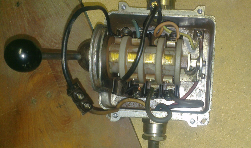
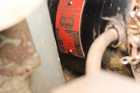
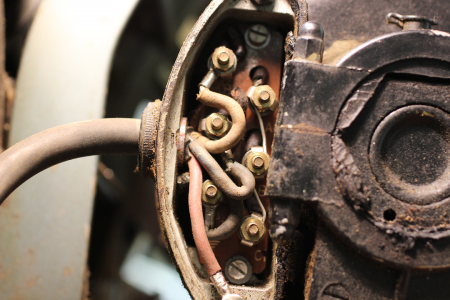
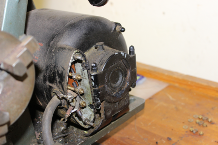
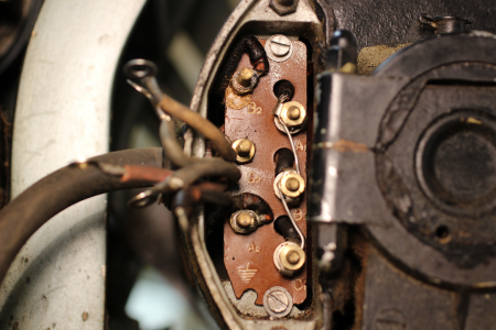
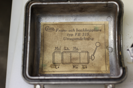
Hope the pictures is enough to go on to ..?
Would really appreciate it if someone could tell me what I´m doing wrong.

Kind regards, Dave.
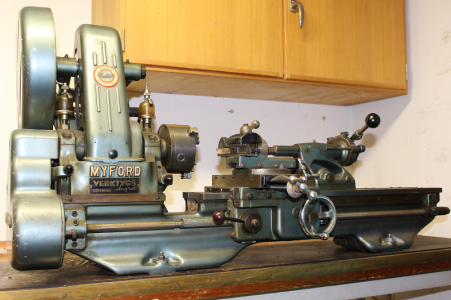
1_My-new-Myford-ML7-Lathe.png 2_Drumswitch-wiring-before-transport.png 3_BROCK-MOTORS-LTD-GRYPHON_3phase-3hp.png 4_Brook-Gryphon-wiring-at-connection-plate.png 5_Brook-Gryphon_overview.png 6_Brook-Gryphon_connection-plate.png 7_Drumswitch-wiring-diagram.png
 
Not familiar with power supply in your part of the world, but would seem that on your rotary switch maybe the white lead coming in should go to the corresponding lead going out. Just a WAG, but if your blowing fuses something is crossed up. Mike
 
Looking at the photos it looks like a 3 phase motor and switch to me - different to my single phase ML7. The Brown, Blue, Green/Yellow wiring shown in the rotary switch photo would imply you only have a single phase supply. Attached is the wiring diagram from the manual if that is of any help.
 

Attachments

  • Pages from [Myford ML7 User Manual (Nr.720S)].pdf
    303.1 KB · Views: 16
Last edited:
It is unusual to use red wire for ground connections (not that the electrons know the difference). Could you sketch out what you believe it ought to be: from the mains, to the switch, to the motor (include any disconnects or breakers / fuses along the way)? Please scan and post the sketch.
 
Hi, Thanks for reply so fast, and early in the morning to, for some of you. :)
Its afternoon here in Sweden.
Actually its a 3 phase power supply, maybe a little unclear on the pictures.
Old wiring in Sweden had earth as a red wire.
I´ll try to draw a simple diagram, but it will have to wait till I get home from work, in a couple of hours.
Back later/ David.
 
It is unusual to use red wire for ground connections (not that the electrons know the difference). Could you sketch out what you believe it ought to be: from the mains, to the switch, to the motor (include any disconnects or breakers / fuses along the way)? Please scan and post the sketch.
Yes. The switch wiring doesn't look right.
 
what is the voltage on all 3 in leads?
 
"But... I blow a fuse when I wired it up the same way it was."

Hmmm... Are you certain that you have 3 phase power in your 'household garage'? Not common to have 3 phase in residential setting in the U.S.A.
 
I just had the 3 phase installed.
My drill press works fine from the same outlet.
Since it´s just been installed I´m quite sure the voltage is 120-140V at each lead.
A rund reed wall socket with 5 pins.

The previous owner used the same cable I´m using.
Maybe I need to change the cable to the wall socket anyway, to one with 5 leads?

Thanks for the diagram. I will print it and try to "wrap my brain around it". ;)

I'll take a photo of the wiring inside the cable socket, the way it was, and post it, so you see how it was when it worked earlier.
Then I think I´ll find a piece of cable with 5 leads, and change to that.

Back soon/David.
 
What did you un wire? How far did you un wire just the motor , the switch and the motor? Check the switch lead to the plug. Make sure that the ground goes to the place it is supposed to go. More than likely that is the problem. I've seen it a hundred times. I once had a guy wireing for me that almost all the motors he wired blew fuses till I figured he was color blind.
 
Back
Top