What kind of tooling is needed to radius a flywheel?

WobblyHand

H-M Supporter - Diamond Member
H-M Lifetime Diamond Member
Joined
Dec 18, 2019
Messages
7,430
I have a small cast iron flywheel that I want to turn into a gyroscope. Have a basic design cobbled up. I knew, and can plainly see I need to radius the flywheel so it fits in the cage or ring. I can fudge it, but how would one do this "for real"? Flywheel is 2"OD. Ring is 2"ID. So I need to radius the wheel so it doesn't interfere with the ring. That makes it a hair under a 1" radius.
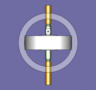
frontviewgyro.jpg
Can this be done with a ball turner?
 
I have a small cast iron flywheel that I want to turn into a gyroscope. Have a basic design cobbled up. I knew, and can plainly see I need to radius the flywheel so it fits in the cage or ring. I can fudge it, but how would one do this "for real"? Flywheel is 2"OD. Ring is 2"ID. So I need to radius the wheel so it doesn't interfere with the ring. That makes it a hair under a 1" radius.
View attachment 426037
Can this be done with a ball turner?
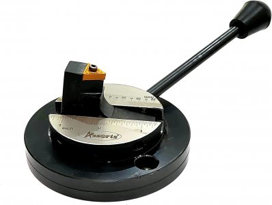
It can be done, if you have a large enough swing on your ball turner. Actually even a 3" style boring head type ball turner could probably do it... but most people dont use that type. The raised cutting insert on a pillar on the outer perimeter of a disc can.. if the tool height is 1" or more.


You'd need to mount your ring on a mandrel, i'd turn the mandrel between centers, and press fit the ring in place or use loctite and then heat to remove after machining. OR if your inner rotor assembly is rigid enough just mount that assembly between centers and ball turn the outside diameter

61xbN5AkdWL._AC_SL1500_.jpg
 
Last edited:
It can be done, if you have a large enough swing on your ball turner. Actually even a 3" style boring head type ball turner could probably do it... but most people dont use that type. The raised cutting insert on a pillar on the outer perimeter of a disc easily can
Don't currently have a ball turner - it has been on the round tuit list a while. Can you explain your last sentence in different words? Think there is something there that I should understand, but am not grasping it yet.
 
Don't currently have a ball turner - it has been on the round tuit list a while. Can you explain your last sentence in different words? Think there is something there that I should understand, but am not grasping it yet.
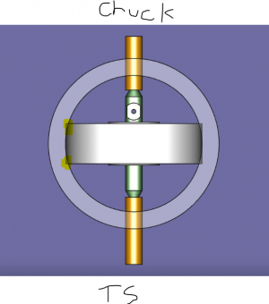
Imagine your pic is the plan view of the rotor assembly mounted between centers, with a lathe dog turning the end at the chuck... and the other held in place via a live center..
Mounted on the cross slide with the cutter at the centerline, and at least one inch between the cutter and the ball turning mount will allow you to swing a 2" rotor.

Then as you swing the ball turner from right to left you will trim off the corners to create a radius that will fit your assembly.
to deepen the cut you move the cutter inwards using the cross slide or by adjusting the cutter offset from the center of the holder. You can make the outer radius of the ring just slightly smaller than the inner diameter of the outer armature

1667947364263.png

Does that make sense to you?
 
watch this... but instead of a rod in the chuck, imagine your rotor as a disc turning between centers.

when using a ball turner like this you will not get a ball, but a disc with a radiused edge. The radius is determined by how far you offset the cutter from the centerline.


Obviously when putting a radium on a disc you barely have to swing the ball turner from side to side
 
You'd have a much nicer time making that arc with a Holdridge type radius cutter. For reasons that will become obvious once you try, the type of cutter above has some serious limitations (the word is "one trick pony").
 
You'd have a much nicer time making that arc with a Holdridge type radius cutter. For reasons that will become obvious once you try, the type of cutter above has some serious limitations (the word is "one trick pony").
You mean something like this?
 
For a one off, how about just approximating the corners with the compound on the lathe, and then smoothing it with a file/sandpaper?
That would work, but won't be all that nice or uniform if done by (my) eye. Been looking at radius tools for a while, but haven't had sufficient need. Hoping to make a couple of these gyros, though. Eventually one of them might be nice enough to give away...

At the moment, I don't even have a way to grab the flywheel except by the OD. Don't have chuck jaws small enough to fit between the spokes or between the hub and the rim. Clearly a classic work holding problem.
When I made one, I made the axle/spindle first, and super glued it to the flywheel as a mandrel. Clickspring on youtube has a video on making a gyroscope that might give you a few ideas.
 
Back
Top