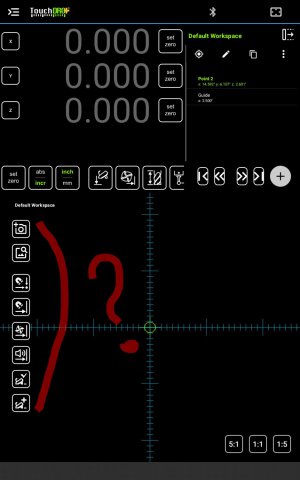
I've searched through the user manual but can't find what these buttons do. Can anyone explain or point me to the spot in the manual where it explains it? Thanks. The pictures on the buttons will probably make sense to me once someone points out the obvious to me.
-
Welcome back Guest! Did you know you can mentor other members here at H-M? If not, please check out our Relaunch of Hobby Machinist Mentoring Program!
You are using an out of date browser. It may not display this or other websites correctly.
You should upgrade or use an alternative browser.
You should upgrade or use an alternative browser.
What are these buttons and how do i use them?
- Thread starter ziggo_2
- Start date
- Joined
- Jun 7, 2013
- Messages
- 10,443
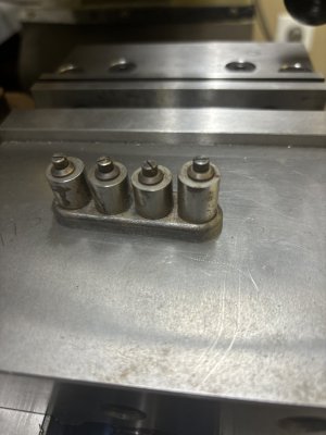
f we are speaking of toolmaker's buttons, they are precisely sized hardened steel cylinders, made hollow so that they may be fastened to a precision surface with a screw, they are used to locate precision features on a plane surface with precision tools such as gage blocks, micrometers or similar measuring instruments for the production gages or drill jigs, etc. They are not much used in the modern era, what with the advent of jig borers and CNC (especially). I have only ever used them once to locate hole centers for an indexing device.
- Joined
- Apr 4, 2013
- Messages
- 845
Well, on an remote off chance that we are not speaking of toolmakers buttons... 
From the top:
#1 - takes a photo and opens the dialog where you can set it as a reference image for the display
#2 - opens a photo for the same purpose.
User manual page for it is here: TouchDRO Reference Image Overlay. This post: Reference Image Function in TouchDRO Plus has some more info.
#3 - turns on automatic sub-datum selection (i.e. as you move towards a coordiante, it will be automatically selected)
#4 - same for guide lines (user manual here: Working with TouchDRO Guide Lines)
#5 - turns on automatic tool offset direction changes (when #4 is turned on). (same user manual page as above)
#6 - turns on automatic proximity/"near-zero" warning (same user manual page as above)
#7 - auto-selection of sub-datum on spindle down/up movement
#8 - automatic creating on sub-datum on spindle down/up movement (useful when you need to perform multiple operations, i.e. spot drill, drill, countersink, tap. On the first operation the DRO will add the coordinate, then turn on #3, and just move between the saved sub-datums.
Hope this helps
Yuriy
ThanksWell, on an remote off chance that we are not speaking of toolmakers buttons...
From the top:
#1 - takes a photo and opens the dialog where you can set it as a reference image for the display
#2 - opens a photo for the same purpose.
User manual page for it is here: TouchDRO Reference Image Overlay. This post: Reference Image Function in TouchDRO Plus has some more info.
#3 - turns on automatic sub-datum selection (i.e. as you move towards a coordiante, it will be automatically selected)
#4 - same for guide lines (user manual here: Working with TouchDRO Guide Lines)
#5 - turns on automatic tool offset direction changes (when #4 is turned on). (same user manual page as above)
#6 - turns on automatic proximity/"near-zero" warning (same user manual page as above)
#7 - auto-selection of sub-datum on spindle down/up movement
#8 - automatic creating on sub-datum on spindle down/up movement (useful when you need to perform multiple operations, i.e. spot drill, drill, countersink, tap. On the first operation the DRO will add the coordinate, then turn on #3, and just move between the saved sub-datums.
Hope this helps
Yuriy


