Not really a day project more like a couple of weeks.
This is my latest project, a welding positioner. I have a shaft and sprocket to weldup and I thought it would be a nice project. I checked the cost of a commercially available unit, but the prices are ridiculous. So why not attempt at building one.
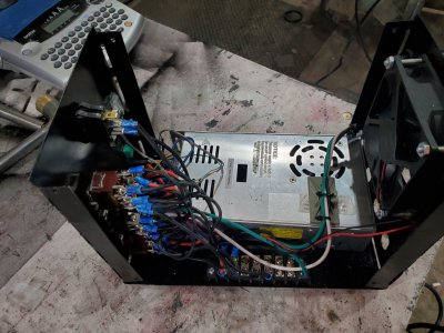
This all started this past winter. It was along drawn out process, from designing the unit, finding parts order parts, make a control box because I could fine one the right size.
So I purchased a 10 amp 120VAC to 48 DC variable controller. Now design the rest. I had to come up with some sort of electrical schematic that would give me directional control, speed, foot control and why not add a tilt, not that it's really needed, but I had a linear actuator. Now find and order flange bearings that with fit a 1" piece of pipe. Now how am I going to drive this thing. I used a Via are compressor motor, but it turned to to be too fast, so a wiper motor I had laying around. Now figure chain size,, sprocket sizes, after some trial and error I settled on a 72 tooth drive sprocket and 12 tooth driver for # 35 chain. One of the most expensive parts was a sheet 4'x4' body metal for the control box, $90. The 3 jaw chuck was only $80 from Vevor.
The cross piece is 2x2x3/16 square tube. The ground mechanism it a piece of pipe with a solid piece of copper rod spring loaded to push up on the drive sprocket. A piece of braided copper was solder to the copper rod and connected to a piece of 3/16 copper plate welded to the frame, easy enough to attach my ground clamp. I wanted to keep the overall weight down so the frame is built using 1/2 electrical EMT brazed together.
All in all it was a much longer project than I thought it would be, because everything had to be made and the design was constantly changing.
I'm sure some of you will find some faults and improvements so your comments are welcome.
The total cost was around $275, Not bad compared to $1800 for a manufactured unit.
Here's a vid of it inaction
Last edited:

