- Joined
- Jun 12, 2014
- Messages
- 5,061
I was interested in assessing how well a proximity sensor would work as an electronic stop on a VFD controlled lathe instead of using a soft/hard stop or mechanically disengaging the feed. There are many different variants on proximity sensors, and I was looking for the following requirements:
1. PNP type to switch the power side of the VFD control inputs and normally closed (NC) type (i.e. conducts the VFD signals until it encounters and object).
2. Works off 12-24VDC (usual VFD signal or relay voltage) and capable of handling at least 200mA.
3. Quick response time of at least 200Hz and a sense distance of at least .3". Both are extremely important when you are looking at stop times of 1-2 seconds. Also high repeat accuracy, the default spec. is 10%.
4. Shielded sensor, so it is not affected by surrounding objects to the sides or behind the sensor.
There is a great review of these parameters here: http://www.automationdirect.com/static/specs/proxterms.pdf
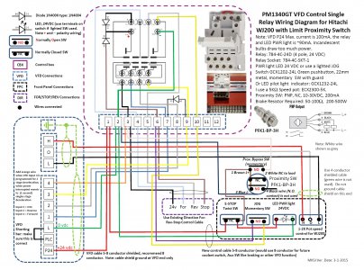
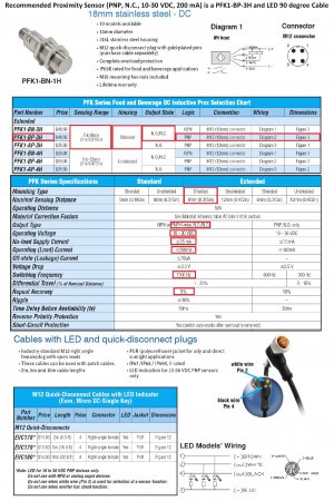
The proximity sensor I ended up using is a PFK1-BP-3H from Automation Direct, which easily meets and exceeds most of these specifications. It is used with a M12 LED quick disconnect plug and cable EVC178 which provides a LED status of the proximity sensor. The sensor information is attached.
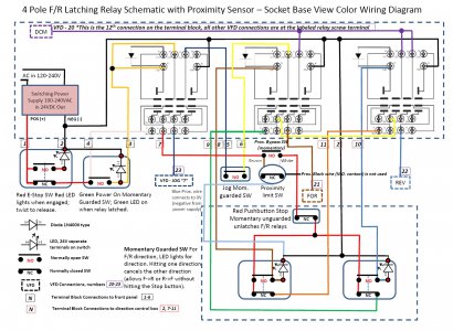
The application of this sensor is for VFD systems only, using either a 12VDC or 24VDC terminal input system using a latching power relay and a maximum current draw of 200mA. The VFD must use an external braking resistor and capable of stopping the lathe chuck in 1-2 seconds. The proximity sensor is being used like an E-Stop switch or brake switch, and is wired in series with these. It it's normal state it conducts the 12-24VDC signals/voltage, when triggered by the moving carriage into range (~0.4"), it goes to an open switch state. This breaks power to the power relay or forward/reverse relay, and the lathe quickly stops. It is imperative that there is some form of reset power button and/or requires the direction switch to be in the stop position when the proximity switch reverts to its NC state as the carriage is mechanically moved backwards. I recommend adding a momentary normally open bypass switch across the proximity sensor's switch wires, which allows one to reverse direction even when the proximity sensor is triggered in its open state. So for threading or machining to a stop, you feed the carriage until the proximity sensor engages, press the bypass switch momentarily and reverse the carriage. The proximity switch will reset to NC in about a second when feeding away from it.
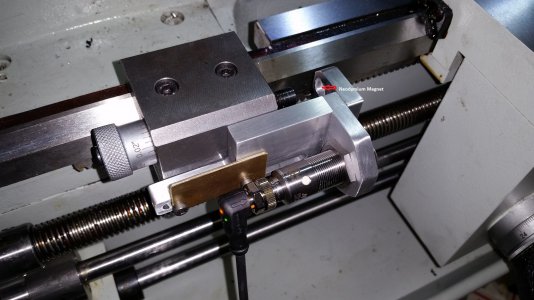
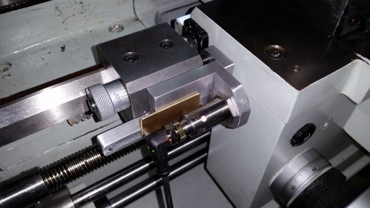
I already had a hard stop, and wanted the proximity switch to work in conjunction with the hard stop micrometer (this is important for safety reasons). I machined a movable slider mechanism to hold the proximity sensor, which slides in a milled channel on round bushings, These set the distance for the outer brass plate. Brass slides a bit better against aluminum, but any kind of sliding mechanism will work. Since the mechanism slides forward as you turn the micrometer, you need a way to pull the mechanism back when you reverse the micrometer direction. I did not want to slot or drill a hole in the hard stop micrometer rod to secure it to the proximity holder, so I glued (epoxy) a small neodymium magnet into the cap. This secures the sliding mechanism to the end of the micrometer rod. The proximity sensor mechanism indexes with the hard stop with 0.001" resolution. The proximity sensor position is adjustable relative to the hard stop, the proximity sensor will activate ~0.1" before the hard stop and this is adjustable.
It should be noted that a hard stop is fixed, and is independent of speed, feed, system momentum and VFD braking capabilities. But it only stops the carriage when feeding. A proximity sensor will be affected by all these variables, so one needs to adjust the engagement point for a specific speed, feed and the momentum of the system.
So the first question is did it work? Yes. If you just look at the proximity sensor's ability to reproduce a stop at the same speed and feed, the reproducibility on multiple runs with this sensor at different RPMs and feeds had a range of 0.0006" using a WJ200 VFD with an external braking resistor (1 second stop time). Small variations in speed and feed had a minimal impact on the stopping point. If one were to double the speed and increase the feed rate, I was able to see a ~0.050" increase in stooping distance, but the repeatability once zeroed for any specific speed and feed was better than 0.001" on repeated passes. I have two short videos of the sensor mechanism and accuracy, but there seems to be no way to upload these videos. I will try to post elsewhere and provide links. I will post a schematic and suggested implementation to follow.


