- Joined
- Apr 21, 2015
- Messages
- 653
I'm restoring a very old Taft Pierce No. 1 Surface Grinder that I bought for just $500. That project is worth its own write up, but I'm too anxious to get it working again to waste time writing it up. Maybe in the future.
I didn't realize it when I bought it, but this is a very early model of this machine indeed. The serial number is 85 which probably means it was built in 1939 from what I can discover (1940 started with serial number 140, apparently). It has plain ways under the saddle instead of roller bearings, no backlash adjustment on the cross-feed screw, and a few other discrepancies from newer versions of this machine.
I've found two versions of the manual, but neither contain a date. Grr.
The older version of the manual has less info, but appears to match this machine better (it describes flat/plain ways, etc.). That version of the manual has no mention of a one-shot oil distribution system, though, which this one clearly has.
The newer manual describes a 9-line oil distribution that matches what's in my machine, but the pictures and text describe a more typical pump/reservoir with a spring-loaded tee-handle mounted on the right side of the pedestal. Mine had the reservoir and a separate lever-actuated pump mounted inside the pedestal (making filling the reservoir more of a hassle for sure).
The only reference to an oiling system in the older manual was the single sentence: "Keep the oil tank filled with a good grade of light ball bearing oil and use the oil pump once a day."
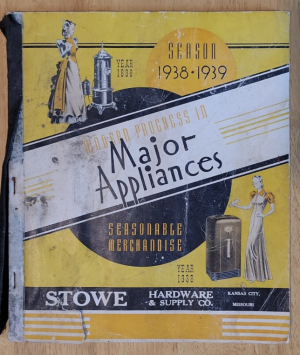
There was a pretty cool sticker on the reservoir, but it completely disintegrated as soon as I touched it, unfortunately. Any guesses as to the manufacturer? I could just make out "...OWE ... TYPE B". Maybe "...OWE CORP TYPE B"?


If anyone recognizes either of those stickers, I'd love to know more. I thought someone had replaced the sight glass with a piece of brass tubing, by the way, but once I cleaned it up sufficiently I realized it actually was still clear glass!
Here's the pump itself:

(Yes, I bought a parts washer just for this project. I may have to dispose of this one and buy another when I'm done ... geez this thing was filthy!)
Now to the point of this post:
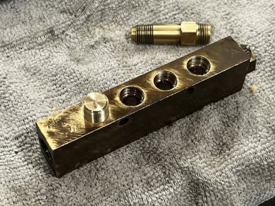
The pump feeds a manifold with 9 metering valves:

Here's a close-up of the valves themselves after a slight cleanup:

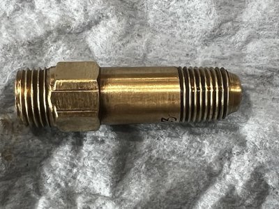
The top part parts are just adapters from from 5/16 to 3/16" OD oil lines with compression fittings. The valves themselves are stamped with "1" or "3" (I think the same flow rates that Bijur uses) but there is no arrow showing direction of flow (which is bottom to top in the last photo) nor any "FSA"/"FJB"/etc like a "modern" metering valve on a Bridgeport or whatever might show.
The new manual shows the type of metering valve I expected:

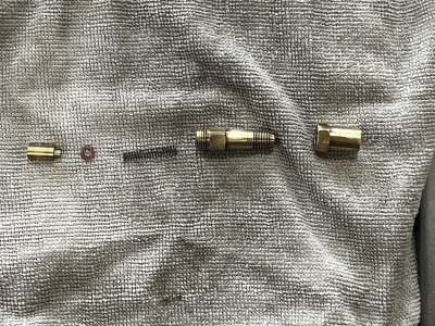
But the actual valves in the machine were VERY different:


The input is on the left and the output on the right. From left to right is:
A metering piston (the #3 is shorter than a #1, allowing more oil to enter the chamber), a paper or phenolic washer, a spring, a one-way valve to prevent back flow, and a 5/16 to 3/16 adapter.
The back flow valve has a spring loaded ball at the end, and a small orifice to allow oil to flow through when the spring resistance is overcome, moving the ball to the right and breaking the seal. I couldn't remove the ball valve for further cleaning without destroying the part, but here's a view from the right end showing the small orifice.

I really didn't want to replace all of these parts if I could avoid it. (It would have been about $180 just for new Bijur valves, and since none of the threads and diameters would have matched, and I REALLY dislike plumbing, I'd have lost my mind trying to find all the correct adapters.
The diameter of the bore where the metering plunger rides was 0.304" on the money for most of the valves (a few were slightly smaller diameter, and one had a pronounce step in the middle that was only 0.301" and appeared to be a defect from the original manufacturing, not dirt or whatever.
I discovered that if I filled the bore with mineral spirits / diesel / whatever, I could flush out the crud by inserting a 0.304" gage pin and making a sort of mini squirt gun. One hard, fast squeeze would overcome the spring tension and blast out the fluid along with whatever crud was in there. The gage pin was a tight enough hydraulic fit that it wouldn't leak (if I pressed hard and fast). I repeated the process multiple times for each valve.
I still wanted to test each line individually, so I wanted to plug all but one line in the manifold at a time. The output ports were some sort of weird 7/16-24 pipe thread. I've never seen that before, but some internet research leads me to believe it might have been used for brake lines on some old cars.
I had no easy way to make plugs with a tapered 7/16"-24 pipe thread. The only way I know to make pipe threads is with a die or with a tapering attachment on the lathe. A specialty die was too expensive for one-use parts, and it wasn't worth a side project to make a tapering attachment, either.
So I made some plugs by single-pointing 7/16-24 straight threads, and lightly filed a slight taper on the OD of the resulting threads. It's not a real pipe thread since the pitch diameter didn't change, but I thought it might seal well enough to flush and test individual lines (I was right).
Here's the first plug before I milled some flats to make it easier to insert/remove:

And here's the test rig to verify the metering function with the original pump (redneck engineering at its finest):

With just one line connected, you barely have to move the pump handle to get a little spurt of oil. The #3 spurts out roughly three times as much as the #1 (whoda thunk?).
I was able to verify that everything worked as expected this way at least.
I've certainly never seen a one-shot lubricating system like this before. If anyone here has any further information about an old system like this, I'd love to know more!
I didn't realize it when I bought it, but this is a very early model of this machine indeed. The serial number is 85 which probably means it was built in 1939 from what I can discover (1940 started with serial number 140, apparently). It has plain ways under the saddle instead of roller bearings, no backlash adjustment on the cross-feed screw, and a few other discrepancies from newer versions of this machine.
I've found two versions of the manual, but neither contain a date. Grr.
The older version of the manual has less info, but appears to match this machine better (it describes flat/plain ways, etc.). That version of the manual has no mention of a one-shot oil distribution system, though, which this one clearly has.
The newer manual describes a 9-line oil distribution that matches what's in my machine, but the pictures and text describe a more typical pump/reservoir with a spring-loaded tee-handle mounted on the right side of the pedestal. Mine had the reservoir and a separate lever-actuated pump mounted inside the pedestal (making filling the reservoir more of a hassle for sure).
The only reference to an oiling system in the older manual was the single sentence: "Keep the oil tank filled with a good grade of light ball bearing oil and use the oil pump once a day."
There was a pretty cool sticker on the reservoir, but it completely disintegrated as soon as I touched it, unfortunately. Any guesses as to the manufacturer? I could just make out "...OWE ... TYPE B". Maybe "...OWE CORP TYPE B"?
If anyone recognizes either of those stickers, I'd love to know more. I thought someone had replaced the sight glass with a piece of brass tubing, by the way, but once I cleaned it up sufficiently I realized it actually was still clear glass!
Here's the pump itself:
(Yes, I bought a parts washer just for this project. I may have to dispose of this one and buy another when I'm done ... geez this thing was filthy!)
Now to the point of this post:
The pump feeds a manifold with 9 metering valves:
Here's a close-up of the valves themselves after a slight cleanup:
The top part parts are just adapters from from 5/16 to 3/16" OD oil lines with compression fittings. The valves themselves are stamped with "1" or "3" (I think the same flow rates that Bijur uses) but there is no arrow showing direction of flow (which is bottom to top in the last photo) nor any "FSA"/"FJB"/etc like a "modern" metering valve on a Bridgeport or whatever might show.
The new manual shows the type of metering valve I expected:
But the actual valves in the machine were VERY different:
The input is on the left and the output on the right. From left to right is:
A metering piston (the #3 is shorter than a #1, allowing more oil to enter the chamber), a paper or phenolic washer, a spring, a one-way valve to prevent back flow, and a 5/16 to 3/16 adapter.
The back flow valve has a spring loaded ball at the end, and a small orifice to allow oil to flow through when the spring resistance is overcome, moving the ball to the right and breaking the seal. I couldn't remove the ball valve for further cleaning without destroying the part, but here's a view from the right end showing the small orifice.
I really didn't want to replace all of these parts if I could avoid it. (It would have been about $180 just for new Bijur valves, and since none of the threads and diameters would have matched, and I REALLY dislike plumbing, I'd have lost my mind trying to find all the correct adapters.
The diameter of the bore where the metering plunger rides was 0.304" on the money for most of the valves (a few were slightly smaller diameter, and one had a pronounce step in the middle that was only 0.301" and appeared to be a defect from the original manufacturing, not dirt or whatever.
I discovered that if I filled the bore with mineral spirits / diesel / whatever, I could flush out the crud by inserting a 0.304" gage pin and making a sort of mini squirt gun. One hard, fast squeeze would overcome the spring tension and blast out the fluid along with whatever crud was in there. The gage pin was a tight enough hydraulic fit that it wouldn't leak (if I pressed hard and fast). I repeated the process multiple times for each valve.
I still wanted to test each line individually, so I wanted to plug all but one line in the manifold at a time. The output ports were some sort of weird 7/16-24 pipe thread. I've never seen that before, but some internet research leads me to believe it might have been used for brake lines on some old cars.
I had no easy way to make plugs with a tapered 7/16"-24 pipe thread. The only way I know to make pipe threads is with a die or with a tapering attachment on the lathe. A specialty die was too expensive for one-use parts, and it wasn't worth a side project to make a tapering attachment, either.
So I made some plugs by single-pointing 7/16-24 straight threads, and lightly filed a slight taper on the OD of the resulting threads. It's not a real pipe thread since the pitch diameter didn't change, but I thought it might seal well enough to flush and test individual lines (I was right).
Here's the first plug before I milled some flats to make it easier to insert/remove:
And here's the test rig to verify the metering function with the original pump (redneck engineering at its finest):
With just one line connected, you barely have to move the pump handle to get a little spurt of oil. The #3 spurts out roughly three times as much as the #1 (whoda thunk?).
I was able to verify that everything worked as expected this way at least.
I've certainly never seen a one-shot lubricating system like this before. If anyone here has any further information about an old system like this, I'd love to know more!