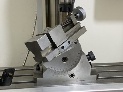
I bought this vice quite many years ago and have used it rarely as there were always alternative ways to get the job done. Now I have got some time and I really want to learn how to use it properly. I believe tramming is always the first step right ? How would you guys do it ?
-
Welcome back Guest! Did you know you can mentor other members here at H-M? If not, please check out our Relaunch of Hobby Machinist Mentoring Program!
You are using an out of date browser. It may not display this or other websites correctly.
You should upgrade or use an alternative browser.
You should upgrade or use an alternative browser.
Tramming a tilt & swivel vice
- Thread starter compact8
- Start date
- Joined
- Feb 1, 2015
- Messages
- 9,995
There are a lot of adjustments there. Nice looking vise, BTW. I would set everything to zero and sweep the base with an indicator to square the vise with the ways. What happens next would depend upon your intended use. Assuming the final setup is as you depicted and you trust the accuracy of the scales, you should be good to go. I read the primary angle as 27º 42'. If you are looking for more accuracy for the angle settings, you would have to use a sine bar, angle gage, or other means to verify the angle. Joe Pieczynski did a You Tube video concerning creating custom angle gages a while back. The idea is to use the gage to create a surface parallel to the bed or to one of the ways and sweep it with an indicator to verify the angle. The compound angle settings make this a bit tricky as I would use the vise to hold my gages but it can be done. I would do the primary angle with the secondary angle set at zero and make as accurate a reading on the scale as I could. Then I would set that angle to zero and set the secondary angle to the desired value, mount my gage for that angle and sweep it. Then I would set my primary angle to the corrected setting and you shoyld be good to go. With careful work, you should be able to hit your angles to a minute or two of arc.
It is this very first step that I am not sure how to do ......... set everything to zero and sweep the base with an indicator to square the vise with the ways....
I believe the purpose is to align the tilting axis with the Y rail of the mill , makes sense but the problem is I am not sure which surface is a good reference for sweeping the DTI over. I know how to align the axis of rotation of the spindle with the way on a lathe but the problem is the tilt of the vice can only be changed by +45 / -90 degrees so finding the center of rotating is not quite possible. The vice did not come with any manual so I have to figure it out by myself.
- Joined
- Feb 1, 2015
- Messages
- 9,995
I am making an assumption that the vise is constructed so the tilting axis is perpendicular to the base edge and that it is parallel with thbottom of the base. Yes, this is an assumption and as they say, "trust but verify". Alignment is complicated by the second rotational axis so using the vise fixed jaw as a reference surface isn't a good way to go unless you can verify that the scale is accurate.It is this very first step that I am not sure how to do .....
I believe the purpose is to align the tilting axis with the Y rail of the mill , makes sense but the problem is I am not sure which surface is a good reference for sweeping the DTI over. I know how to align the axis of rotation of the spindle with the way on a lathe but the problem is the tilt of the vice can only be changed by +45 / -90 degrees so finding the center of rotating is not quite possible. The vice did not come with any manual so I have to figure it out by myself.
For an initial check, I would align the base as described previously and set the tilt angle at 0º and the swivel angle at 0º. I would mount a piece of bar stock in the vise with about 1/2" above the jaws. Face the top of the bar stock. Next, set the tilt angle at +60º and side mill the bar to create half a dovetail. Finally, rotate the tilt to -60º and check the corner of the cut with an edge finder or the cut surface with a test indicator.
If the tilt axis is true, you will see no change in the reading. If not, well Houston, we have a problem. Misalignment either horizontally or vertically will cause a difference in readings. Parsing that will be more challenging.

