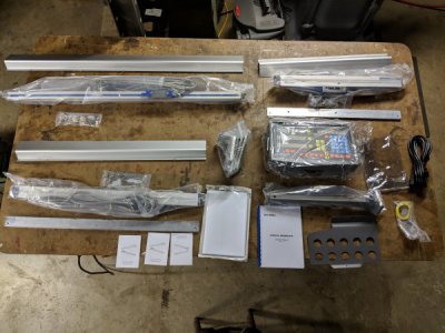
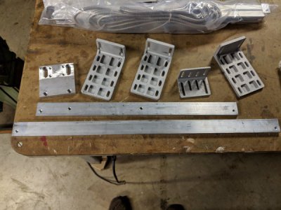
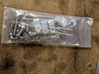
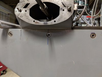
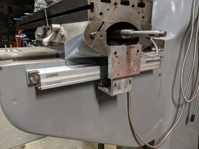
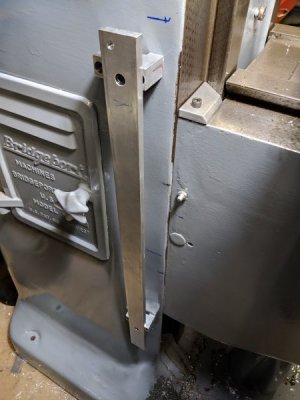
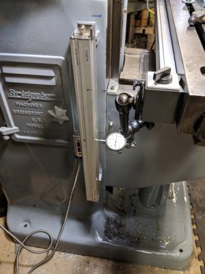
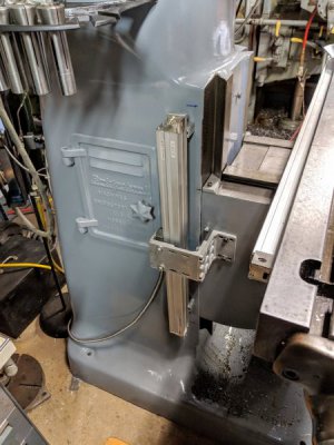
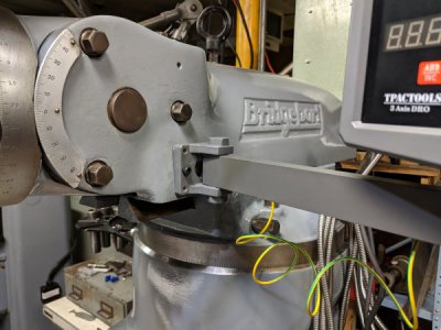
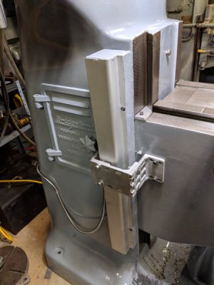
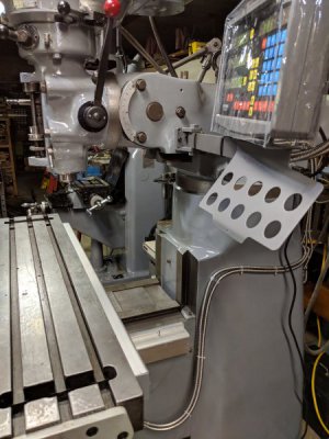
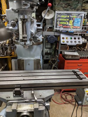
I started with the X axis, which is done except for installing the cover and securing the cables (I'll do all of that at the end). The X is suppose to be the easiest because the surfaces are the flattest. I decided to go with inch hardware so I'm using some slotted head screws in some places temporarily. I just got back from my local hardware store where I bought the correct length hex socket head cap screws and they cost $.95 each! Oh well, beats ordering a box of 50.
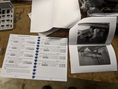
As far as the installation instructions go, if you are looking for step by step, hold your hand type directions, this isn't the kit for you. The information is mostly there, but you have to read the instructions (with tolerance and setup dimensions) that's in the paperwork that comes with the slides/heads in addition to the main instruction packet. All the instructions are written in broken English, but I've seen worse and you can make sense out of them. The only thing so far that wasn't covered at all were the blue plastic clips that come mounted between the slide and the head. I didn't know if these were for installation spacing or just for shipping protection, but after finding the recommended spacing between the slide and head on one of the sheets it was obvious that they couldn't be used for installation and it suggests using a spacer for this purpose. I found a piece of cardboard in the middle of the range and used that. Most of the mounting is intuitive and if you think about how things work, the travel involved and put your machinist hat on, you'll be fine.
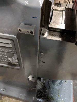
There are two ways you can mount the head for the X axis. One (the way I did it) was to face mount it with two screws through the head without using a bracket. The second way was to use an angle bracket. I chose the first way because it seemed the simplest, but if I were to do another one I would go with the bracket mount because I think in the long run it would be easier, even though more operations are involved. Reason being to face mount it like it did the mounting holes are long, all the way through the body of the head and there is not much clearance between the mounting holes and the screws, so you better drill and tap your holes dead on so you can maintain the proper alignment and spacing. I used a transfer punch and did the first hole, then using a screw in that hole punched the second hole. It's a good thing I double checked the punch mark because it was NOT close enough! I had to correct it by walking the center punch mark into the correct location by punching sideways with a center punch. It turned out fine, but extra work and if I hadn't double checked it would have been an issue. If using a bracket, if the holes were a little out of location you could easily open up the holes in the bracket to accommodate, but doing the same in the reader head would be tricky since you'd have to come up with a way of holding it safely and I don't like the thought of doing it! So, I would suggest to anyone doing this to use an angle bracket. The good news is the cast iron drills easily.
So, overall, so far anyways, better instructions would have been nice, but certainly not worth the additional $287 and the lesser warranty for the unit from DROpros. Please don't think I'm bashing DROpros, because I certainly am not... I'm just expressing that I don't mind having to figure a couple of things out on my own to save close to $300. Someone else may feel differently and that's fine.
We'll see how the rest of the project goes. So far, so good.
Ted
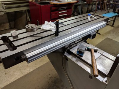
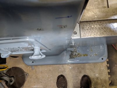
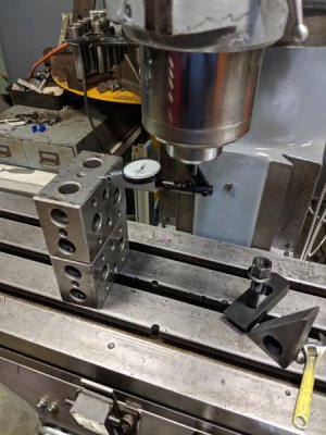
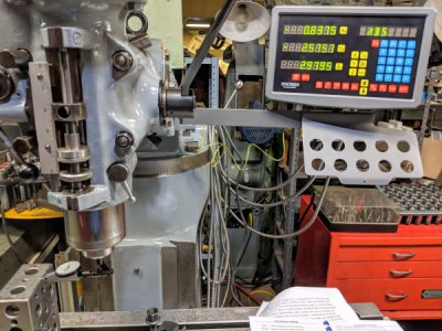
Using the mag bases to help hold things in position while I work. Also, used a drill guide (rectangular bar with drilled hole in it) and a tap guide to help keep things straight.
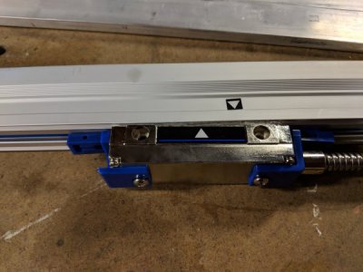
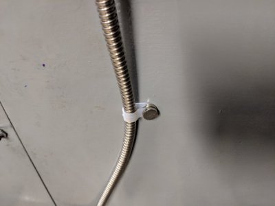
The blue clips that come on each head for shipping protection.
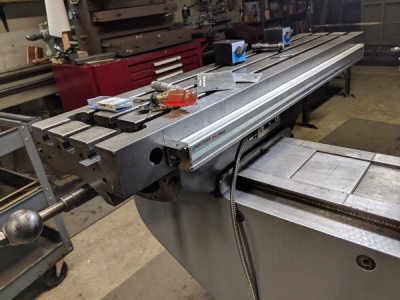
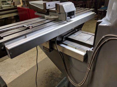
All done and aligned! I'll install on the covers and secure all the cables when everything is mounted and ready to be calibrated. You don't have to remove the power feed unit, but I wanted to get it out of the way, especially for the Y axis install.
