- Joined
- Jan 3, 2013
- Messages
- 78
I am now able to submit this thread due to the valuable assistance of Robert D. also known as wa5cab. Thank you Robert! A corrupt photo froze the system, I removed it.
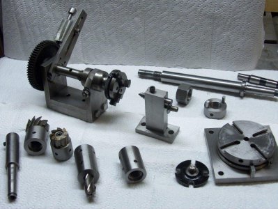
Photo 700, shows a collage of home shop made tools that will work on the Atlas Milling machine.
Front left, shows end and shell mill holders. Holders mounted on the threaded spindle are far more rigid than the Morse taper holder. I don’t have a tap this size. The threads are cut with a single point inside threading tool. To check the thread fit, unscrew the lathe chuck to test thread fit on the mill spindle as you proceed. Do not take the work out of the chuck until it is complete. All of the precision machining is completed in one setup working from the threaded end. Drill thru, bore the thread area, bore through the mill shank section, ream to finish size. Cut the threads and face the end completes the machining and all will be concentric.
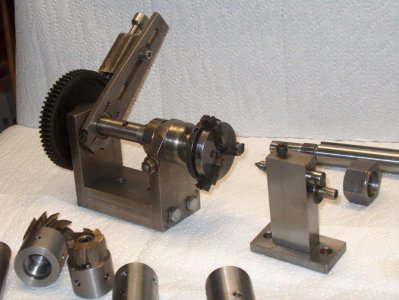
The horizontal indexer is a bolted and doweled assembly. Lathe change gears are used for indexing and the work may be held between centers or by the Unimat chuck. Center height is approx. 3 inches.
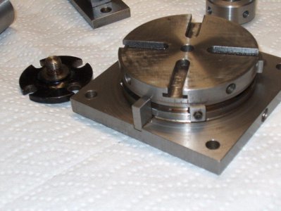
The manual rotary table is a George Thomas (I believe) design from Model Engineer Magazine an English publication. The issues it was in was early 1970’s. I modified the design to suit material I had access to.
The base is 5 X 5 and the Table is 4 Dia. stock cleaned up for precision. The rim area (4 dia. X 3/8 ) takes the vertical thrust. The pivot is a turned diameter approx. 3.25 inch diameter boss on the base plate 3/8 high. This was machined slip fit no shake with respect to the table. This reduced the number of parts, provides tremendous bearing area, and when assembled with light grease rotates smoothly. Stops are clamped into a circular dovetail groove, around the periphery of the table, a very educational endeavor as I remember. The periphery is divided in degrees. For circular machining, the work is centered on the table and clamped, the stops set for the number of degrees of radius needed, and rotated with a 3/8 rod approx. 12 inches long. Take light cuts. Guy Lautard (www.lautard.com ) sells plans for a similar rotary table.
The black device is a Unimat chuck adapter for the rotary table.
The tools described thus far have been used for up to 25 years.
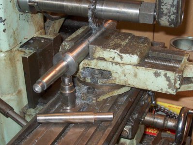
The newest item is the one inch arbor. I measured the 7/8 arbor that came with the Atlas Milling machine, and made it the same except the diameter. A purchased Morse taper was used, the short taper end was turned straight, the tang cutoff and the small end of the Morse taper was drilled and tapped for 3/8 – 16 for the draw bar. I pinned it to a piece of bar stock. This assembly was put into the head stock taper of the lathe, and carefully center drilled. With tail stock support the arbor was completed. An additional nut and a driving collar was machined to complete the project. One inch ID arbor spacer set was ordered on line.
Work very carefully, as errors in tooling, will be passed on to all subsequent jobs the tool made, is used for!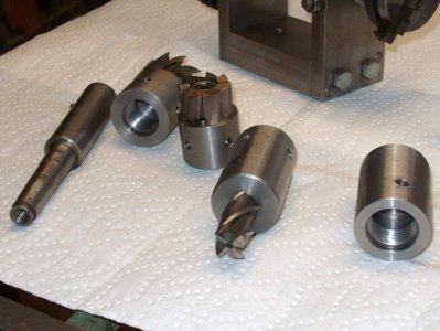


