- Joined
- Aug 14, 2011
- Messages
- 101
Over the past few years I have written numerous articles outlining projects that could have value to the hobbyist. Most of these focused on improving the equipment usually the lathe or the mill. One fact that has always bothered me is the relative low number of hobbyists that venture forth to try new features or methods on their equipment. A case in point is threading on the lathe. The purpose of this post is to generate interest in threading by those who are reluctant to try the process.
During the past year or so I have slowly switched to using carbide inserts for threading. I was a reluctant convert but after using carbide on a number of projects I am a believer. So, one of the tools to make the threading process easier is to use a carbide tool holder and insert. I use the ones made by Mesa Tools they are inexpensive and compact and a single insert will handle 11-48 TPI. There are numerous other insert vendors so look around. Using an insert eliminates the grinding process that some fear as much as threading.
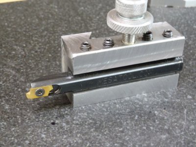
Photo #1 – Carbide threading tool and insert.
A second tool that can help in threading is the retractor. There are retracting tool holders (photo #2), retracting cross slides (photos #3) and retracting top slides (photo #4). These all provide the ability with a flip of a lever to withdraw the tool quickly thus allowing you to prepare to stop and reverse the carriage.
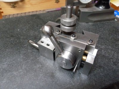
Photo #2 – Retracting tool holder from the “Model Engineers Workshop Manual” by George Thomas. This was my first retracting device and it worked well for many projects.
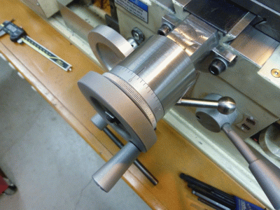
Photo #3 – A retracting cross slide. This moves the entire cross slide back by about 0.250”. This was my second retractor and a favorite since it is useful for operations other than threading.
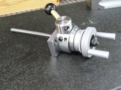
Photo #4 - This is my latest retractor and is used to retract the top slide on the Grizzly G0602.
Photo #5 shows both the cross slide retractor and the top slide retractor installed in the Grizzly G0602. Details on the cross slide retractor can be found here:
http://www.projectsinmetal.com/forum/general-discussion/making-a-g0602-cross-slide-retractor/
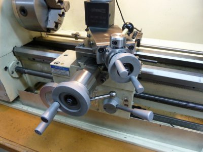
Photo #5 – Both retractors installed on the G0602.
I designed the top slide retractor as an easier project and hope that will have wider appeal. The following video link will show the top slide retractor in use while threading.
https://vimeo.com/86786262
While both of these retractors were designed for the G0602 they are readily adaptable to a wide variety of other lathes, do not be afraid to experiment. The following will provide the detail needed to construct the top slide retractor for the G0602.
We start with a piece of mild steel 1.5 x 1.25 x 3”, I used 1018 but other types will work fine. Diagram #1 gives the dimensions for the main body as viewed from the front and diagram #2 is a rear view.
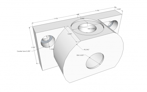
Diagram #1 – Main retractor body as view from the front.
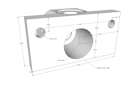
Diagram #2 – Main retractor body as view from the rear.
Square up the steel billet and then drill a 0.375” hole through the billet at the location that will become the cavity for the bearing carrier. The exact location is shown in diagram #2. This hole will be used to locate the billet for subsequent operations the first of which is to machine away the excess material around the cavity. I used a rotary table to mill away the material but you may also use a face plate adapter and machine it on the lathe. Next bore the cavity for the bearing carrier and then drill and bore the top opening and recess which will hold the eccentric bushing. Next drill and counter bore the holes for the socket head screws used to attach the body to the top slide. You should now have the complete body and be ready to machine the other components starting with the bearing carrier shown in diagram #3.
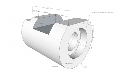
Diagram #3 – Bearing carrier, material is mild steel or drill rod.
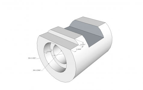
Diagram #4 – Bearing carrier, rear view.
The carrier should be a close fit to the main body and be flush with the rear side when inserted all of the way. The flat on the top of the carrier will provide clearance for the eccentric bushing and prevent rotation of the carrier. The step on the rear edge allows for clearance for the top slide table when retracted. The slot for the slider is nominally 0.500”, a few thousands one way or the other is not a problem as you can adjust the width of the slider when you make that which is next.
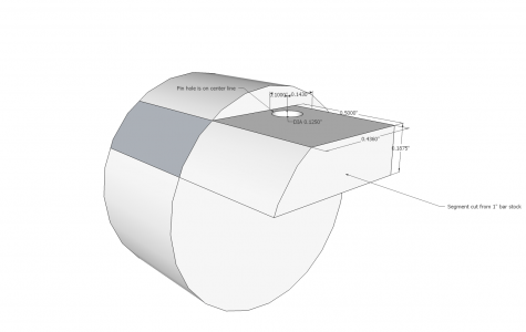
Diagram #5 – Bearing carrier slider, cut from one inch bar stock.
I used a slitting saw to cut the segment from the bar stock after milling it to the correct dimensions. The fit of the slider is important, we want a good fit without drag. The slider will lock the bearing carrier in position when the retractor is returned to the home position.
Next up is to make the eccentric bushing. The eccentric is needed to position the slider/bearing carrier assembly at exactly the rearmost position when the retractor is locked in the home position. This allows us to accommodate a certain amount of tolerance buildup during the machining process. Diagram #6 shows the dimensions the bushing is turned from a piece of 1” stock.
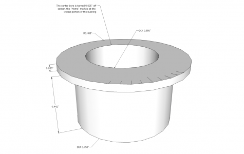
Diagram #6 – Eccentric bushing.
Turn the outer dimensions then part off the piece. If the top lip is more than 0.050” chuck the bushing up and face off the excess. Next place a 0.035” piece of shim stock between the bushing and one of the chuck jaws. This will provide the offset needed. Drill and bore the center hole to dimension shown.
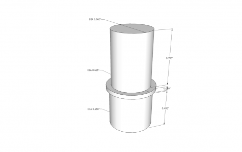
Diagram #7 – Retraction shaft, turned from 0.625 mild steel or drill rod.
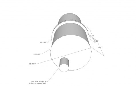
Diagram #8 – Dowel pin is press fitted at a point 0.150” off from the shaft center line.
We should now have the main body, the bearing carrier with slider, the eccentric bushing and bushing shaft. Next we need to drill the pin hole in the slider this will require some measurements with the pieces in place. The objective is to locate the hole on the center line of the bushing center bore and 0.150” off of the center of the bushing when the bearing carrier is in the home position. If you are off a few thousands that can be compensated two ways the first is by rotation of the bushing to place the bearing carrier against the bottom of the cavity. The second is that the slider can be filed on “rounded” edge which will move the hole further off center. You will probably need just the bushing adjustment to achieve the desired result. If you place a small amount of hi-point blue on the top of the slider and then insert the shaft and rotate it back and forth you should have a arc that closely marks the point where you will drill the hole.
Once you are satisfied with the fit and adjustment of the bearing carrier there are several more operations to do on the main body. The first is to drill and tap a 4 x40 hole at the 7:30 o’clock position when looking down on the main body. This will take a 4x40 socket head screw that will clamp the eccentric bushing in place after it is adjusted and the head of the screw will serve as rotation stop for the actuator handle. Diagram #9 provides the needed dimensions.
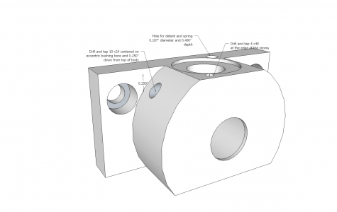
Diagram #9 – Hole locations for the bushing retainer screw, bushing clamp screw and the detent hole.
After drilling, tapping and counter boring the 10 x 24 retainer hole insert the bushing in the orientation that you ended with when adjusting the slider and bearing carrier. In this position the narrowest part of the bushing should be closest to the side of the main body or very close to it. Use a drill point or other object to mark the location on bushing. Place the bushing in the mill and mill a 0.187 slot for a distance of about 0.125” then rotate the bushing in the vise slightly and continue to lengthen the slot in both directions. When complete you should be able to rotate the bushing through an arc of about 30 degrees. Insert the bushing into the housing and screw in a socket head 10 x 24 and mark the length needed protrude through the bushing and engage the shaft by 0.050”. Next mark the shaft and turn a groove that the screw will engage. This will act as the shaft retainer.
The last operation on the body is to drill a 0.187” hole to a depth of 0.400”. The hole is located 180 degrees from the 4 x 40 clamping screw and the edge of the hole should be as close to the top recess edge as possible. When I got to this part of the project I ran out of real estate to locate some of the remaining items and the detent suffered. It will only partly engage the handle base but it does perform the task of retaining the position of the handle.
The recesses in the ends of the bearing carrier take deep groove 10 x 15 x 4 mm shielded bearings. I purchased these from VXB on the internet. An alternative is make a bronze disc that fits the recess and use a bronze bearing on both ends.
The action for retracting the top slide is inverted from retracting the cross slide. On the cross slide the lead screw nut is held by the moveable table, on the top slide the nut is held by the base. This means that when retracting the top slide the calibrated dial has to go someplace. To accommodate the need I made a simple tubular sleeve that the dial slides into when retracting. To illustrate this look at photos 5 and 6.
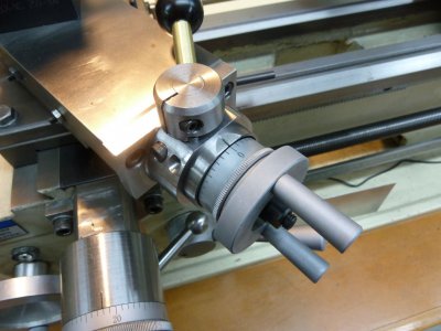
Photo #5 – The top slide is in the “home” position, note the calibrated dial marking are exposed.
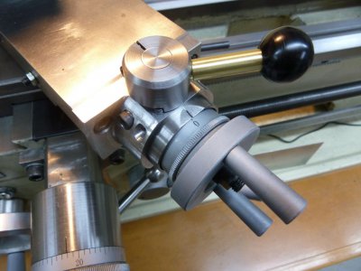
Photo #6 – The top slide is now retracted, note the calibrated dial has slid into the sleeve and the marking are now hidden.
Diagram #10 provides the dimensions for the sleeve which is made from a short piece of 1.75” steel. I milled both sides flat and then chucked it up to drill the center out to 0.375” and then turn the recess to a depth of 0.150” which is the calculated total retract distance. The diagram shows the center hole at 0.625”, at this point in the process leave the hole at 0.375” and this will be used to locate the sleeve on the main body for drilling and tapping.
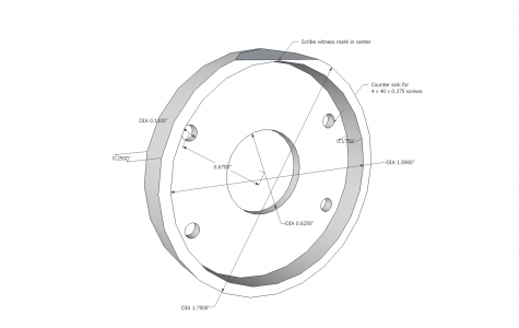
Diagram #10 - The dial sleeve.
I used the bolt hole pattern function on my DRO to locate the screw holes but the XY coordinates for these holes are as follows.
Starting at hole #1 which is at the 2:00 o’clock position and then proceeding clockwise.
X = + 0.5802 Y = + 0.3350
X = + 0.5802 Y = - 0.3350
X = - 0.5802 Y = - 0.3350
X = - 0.5802 Y = +0.3350
Mount the main body and clamp the dial sleeve to it by using a short 0.375” bolt and nut. Drill the holes to 0.500” in depth and tap then counter sink the top for a flat head 4 x 40 screw. The counter sink should come out almost to the edge of the sleeve. Once this is completed mount the main body with the sleeve in a vise and tilt it to 12 -15 degrees and mill the flat shown in the diagram. Next scribe a witness mark in the center of the flat. With both piece screwed together place the assembly back in the mill vise and open up the center hole to 0.625”. Photo #7 shows the pieces that we have completed.
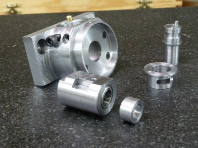
Photo #7 – The completed major components.
Diagram #11 gives the detail for the handle and base. The important part is to make sure that the detent engages fully as the base rotates up against the stop placing the retractor in the “home” position. Make the detent from a short piece of 3/16” diameter spring and a short piece of brass rod with the top rounded.
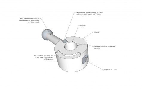
Diagram #11 – Bottom view of the handle base showing the recesses for the detent and stops.
Two items remain the first is a new lead screw and the second is a spacer that fits between the outer bearing and the knob. Lets start with the lead screw. Diagram #12 provides the needed detail but before you start on the lead screw lets discuss threads. The lead screw is threaded 8 x 1mm which means that one rotation of the screw moves the top slide 0.0394”, not exactly the 0.040” the dial indicates. The cross slide suffers the same error for the same reasons. You may or may not want to correct this most people acknowledge the error and learn to live with it. If you decide to correct the error you need to thread at 25 TPI which the G0602 cannot do directly but it can come very close. By using a top gear (“A” gear) of 45 and bottom gear of 52 and setting the gear box to II A and using the output from the 127 tooth gear to drive the gear box you will have a thread of 24.96 TPI this reduces the error to one ten thousand. Not too bad. Lets assume that you will stick with using the 1mm thread pitch and leave the error reduction for a later time.
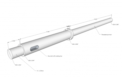
Diagram #12 - Details for the lead screw.
Use a ½” piece of steel rod, I used drill rod. Turn the handle end to the dimensions shown above and thread the end 8 x 1.25mm. You can mill the key slot later. Then reverse the rod and center drill the end and mount the rod so that you can thread it over the entire length. Thread it for either the 25 TPI or 1mm, your choice. One hint since you will not be able to test fit the screw to the top slide nut an option is to thread the screw to spec and when you are satisfied with the thread test fit it to the nut. If you are not satisfied with the fit and easy alternative is to cut a piece Delrin to the diameter of the hole that the nut is pressed into. With the Delrin in place position the top slide base on the mill and drill out the Delrin to a diameter of lead screw minus one thread depth. Then on the end of the new lead screw mill two flat spots so that when the lead screw is threaded into the Delrin these flat spots will act as a tap. Delrin nuts last a lot longer than bronze.
The last piece is the collar/spacer that fits on the lead screw and fills the void between the rear bearing and the knob. I used a piece of 5/8” rod that was 0.250” long and bored out the center to fit over the lead screw. You can alter the length of this piece so that the dial fits nicely with the dial sleeve. Then mill the key slot on the lead screw shaft.
Put everything together and run through the adjustments. The eccentric bushing should be rotated until the bearing carrier locks against the rear of the housing. Next position the handle so the closed stop is reached just as the detent clicks into position. Once you are happy with this try your first thread. You will find that you can thread at a higher spindle speed which will result in cleaner threads.


During the past year or so I have slowly switched to using carbide inserts for threading. I was a reluctant convert but after using carbide on a number of projects I am a believer. So, one of the tools to make the threading process easier is to use a carbide tool holder and insert. I use the ones made by Mesa Tools they are inexpensive and compact and a single insert will handle 11-48 TPI. There are numerous other insert vendors so look around. Using an insert eliminates the grinding process that some fear as much as threading.

Photo #1 – Carbide threading tool and insert.
A second tool that can help in threading is the retractor. There are retracting tool holders (photo #2), retracting cross slides (photos #3) and retracting top slides (photo #4). These all provide the ability with a flip of a lever to withdraw the tool quickly thus allowing you to prepare to stop and reverse the carriage.

Photo #2 – Retracting tool holder from the “Model Engineers Workshop Manual” by George Thomas. This was my first retracting device and it worked well for many projects.

Photo #3 – A retracting cross slide. This moves the entire cross slide back by about 0.250”. This was my second retractor and a favorite since it is useful for operations other than threading.

Photo #4 - This is my latest retractor and is used to retract the top slide on the Grizzly G0602.
Photo #5 shows both the cross slide retractor and the top slide retractor installed in the Grizzly G0602. Details on the cross slide retractor can be found here:
http://www.projectsinmetal.com/forum/general-discussion/making-a-g0602-cross-slide-retractor/

Photo #5 – Both retractors installed on the G0602.
I designed the top slide retractor as an easier project and hope that will have wider appeal. The following video link will show the top slide retractor in use while threading.
https://vimeo.com/86786262
While both of these retractors were designed for the G0602 they are readily adaptable to a wide variety of other lathes, do not be afraid to experiment. The following will provide the detail needed to construct the top slide retractor for the G0602.
We start with a piece of mild steel 1.5 x 1.25 x 3”, I used 1018 but other types will work fine. Diagram #1 gives the dimensions for the main body as viewed from the front and diagram #2 is a rear view.

Diagram #1 – Main retractor body as view from the front.

Diagram #2 – Main retractor body as view from the rear.
Square up the steel billet and then drill a 0.375” hole through the billet at the location that will become the cavity for the bearing carrier. The exact location is shown in diagram #2. This hole will be used to locate the billet for subsequent operations the first of which is to machine away the excess material around the cavity. I used a rotary table to mill away the material but you may also use a face plate adapter and machine it on the lathe. Next bore the cavity for the bearing carrier and then drill and bore the top opening and recess which will hold the eccentric bushing. Next drill and counter bore the holes for the socket head screws used to attach the body to the top slide. You should now have the complete body and be ready to machine the other components starting with the bearing carrier shown in diagram #3.

Diagram #3 – Bearing carrier, material is mild steel or drill rod.

Diagram #4 – Bearing carrier, rear view.
The carrier should be a close fit to the main body and be flush with the rear side when inserted all of the way. The flat on the top of the carrier will provide clearance for the eccentric bushing and prevent rotation of the carrier. The step on the rear edge allows for clearance for the top slide table when retracted. The slot for the slider is nominally 0.500”, a few thousands one way or the other is not a problem as you can adjust the width of the slider when you make that which is next.

Diagram #5 – Bearing carrier slider, cut from one inch bar stock.
I used a slitting saw to cut the segment from the bar stock after milling it to the correct dimensions. The fit of the slider is important, we want a good fit without drag. The slider will lock the bearing carrier in position when the retractor is returned to the home position.
Next up is to make the eccentric bushing. The eccentric is needed to position the slider/bearing carrier assembly at exactly the rearmost position when the retractor is locked in the home position. This allows us to accommodate a certain amount of tolerance buildup during the machining process. Diagram #6 shows the dimensions the bushing is turned from a piece of 1” stock.

Diagram #6 – Eccentric bushing.
Turn the outer dimensions then part off the piece. If the top lip is more than 0.050” chuck the bushing up and face off the excess. Next place a 0.035” piece of shim stock between the bushing and one of the chuck jaws. This will provide the offset needed. Drill and bore the center hole to dimension shown.

Diagram #7 – Retraction shaft, turned from 0.625 mild steel or drill rod.

Diagram #8 – Dowel pin is press fitted at a point 0.150” off from the shaft center line.
We should now have the main body, the bearing carrier with slider, the eccentric bushing and bushing shaft. Next we need to drill the pin hole in the slider this will require some measurements with the pieces in place. The objective is to locate the hole on the center line of the bushing center bore and 0.150” off of the center of the bushing when the bearing carrier is in the home position. If you are off a few thousands that can be compensated two ways the first is by rotation of the bushing to place the bearing carrier against the bottom of the cavity. The second is that the slider can be filed on “rounded” edge which will move the hole further off center. You will probably need just the bushing adjustment to achieve the desired result. If you place a small amount of hi-point blue on the top of the slider and then insert the shaft and rotate it back and forth you should have a arc that closely marks the point where you will drill the hole.
Once you are satisfied with the fit and adjustment of the bearing carrier there are several more operations to do on the main body. The first is to drill and tap a 4 x40 hole at the 7:30 o’clock position when looking down on the main body. This will take a 4x40 socket head screw that will clamp the eccentric bushing in place after it is adjusted and the head of the screw will serve as rotation stop for the actuator handle. Diagram #9 provides the needed dimensions.

Diagram #9 – Hole locations for the bushing retainer screw, bushing clamp screw and the detent hole.
After drilling, tapping and counter boring the 10 x 24 retainer hole insert the bushing in the orientation that you ended with when adjusting the slider and bearing carrier. In this position the narrowest part of the bushing should be closest to the side of the main body or very close to it. Use a drill point or other object to mark the location on bushing. Place the bushing in the mill and mill a 0.187 slot for a distance of about 0.125” then rotate the bushing in the vise slightly and continue to lengthen the slot in both directions. When complete you should be able to rotate the bushing through an arc of about 30 degrees. Insert the bushing into the housing and screw in a socket head 10 x 24 and mark the length needed protrude through the bushing and engage the shaft by 0.050”. Next mark the shaft and turn a groove that the screw will engage. This will act as the shaft retainer.
The last operation on the body is to drill a 0.187” hole to a depth of 0.400”. The hole is located 180 degrees from the 4 x 40 clamping screw and the edge of the hole should be as close to the top recess edge as possible. When I got to this part of the project I ran out of real estate to locate some of the remaining items and the detent suffered. It will only partly engage the handle base but it does perform the task of retaining the position of the handle.
The recesses in the ends of the bearing carrier take deep groove 10 x 15 x 4 mm shielded bearings. I purchased these from VXB on the internet. An alternative is make a bronze disc that fits the recess and use a bronze bearing on both ends.
The action for retracting the top slide is inverted from retracting the cross slide. On the cross slide the lead screw nut is held by the moveable table, on the top slide the nut is held by the base. This means that when retracting the top slide the calibrated dial has to go someplace. To accommodate the need I made a simple tubular sleeve that the dial slides into when retracting. To illustrate this look at photos 5 and 6.

Photo #5 – The top slide is in the “home” position, note the calibrated dial marking are exposed.

Photo #6 – The top slide is now retracted, note the calibrated dial has slid into the sleeve and the marking are now hidden.
Diagram #10 provides the dimensions for the sleeve which is made from a short piece of 1.75” steel. I milled both sides flat and then chucked it up to drill the center out to 0.375” and then turn the recess to a depth of 0.150” which is the calculated total retract distance. The diagram shows the center hole at 0.625”, at this point in the process leave the hole at 0.375” and this will be used to locate the sleeve on the main body for drilling and tapping.

Diagram #10 - The dial sleeve.
I used the bolt hole pattern function on my DRO to locate the screw holes but the XY coordinates for these holes are as follows.
Starting at hole #1 which is at the 2:00 o’clock position and then proceeding clockwise.
X = + 0.5802 Y = + 0.3350
X = + 0.5802 Y = - 0.3350
X = - 0.5802 Y = - 0.3350
X = - 0.5802 Y = +0.3350
Mount the main body and clamp the dial sleeve to it by using a short 0.375” bolt and nut. Drill the holes to 0.500” in depth and tap then counter sink the top for a flat head 4 x 40 screw. The counter sink should come out almost to the edge of the sleeve. Once this is completed mount the main body with the sleeve in a vise and tilt it to 12 -15 degrees and mill the flat shown in the diagram. Next scribe a witness mark in the center of the flat. With both piece screwed together place the assembly back in the mill vise and open up the center hole to 0.625”. Photo #7 shows the pieces that we have completed.

Photo #7 – The completed major components.
Diagram #11 gives the detail for the handle and base. The important part is to make sure that the detent engages fully as the base rotates up against the stop placing the retractor in the “home” position. Make the detent from a short piece of 3/16” diameter spring and a short piece of brass rod with the top rounded.

Diagram #11 – Bottom view of the handle base showing the recesses for the detent and stops.
Two items remain the first is a new lead screw and the second is a spacer that fits between the outer bearing and the knob. Lets start with the lead screw. Diagram #12 provides the needed detail but before you start on the lead screw lets discuss threads. The lead screw is threaded 8 x 1mm which means that one rotation of the screw moves the top slide 0.0394”, not exactly the 0.040” the dial indicates. The cross slide suffers the same error for the same reasons. You may or may not want to correct this most people acknowledge the error and learn to live with it. If you decide to correct the error you need to thread at 25 TPI which the G0602 cannot do directly but it can come very close. By using a top gear (“A” gear) of 45 and bottom gear of 52 and setting the gear box to II A and using the output from the 127 tooth gear to drive the gear box you will have a thread of 24.96 TPI this reduces the error to one ten thousand. Not too bad. Lets assume that you will stick with using the 1mm thread pitch and leave the error reduction for a later time.

Diagram #12 - Details for the lead screw.
Use a ½” piece of steel rod, I used drill rod. Turn the handle end to the dimensions shown above and thread the end 8 x 1.25mm. You can mill the key slot later. Then reverse the rod and center drill the end and mount the rod so that you can thread it over the entire length. Thread it for either the 25 TPI or 1mm, your choice. One hint since you will not be able to test fit the screw to the top slide nut an option is to thread the screw to spec and when you are satisfied with the thread test fit it to the nut. If you are not satisfied with the fit and easy alternative is to cut a piece Delrin to the diameter of the hole that the nut is pressed into. With the Delrin in place position the top slide base on the mill and drill out the Delrin to a diameter of lead screw minus one thread depth. Then on the end of the new lead screw mill two flat spots so that when the lead screw is threaded into the Delrin these flat spots will act as a tap. Delrin nuts last a lot longer than bronze.
The last piece is the collar/spacer that fits on the lead screw and fills the void between the rear bearing and the knob. I used a piece of 5/8” rod that was 0.250” long and bored out the center to fit over the lead screw. You can alter the length of this piece so that the dial fits nicely with the dial sleeve. Then mill the key slot on the lead screw shaft.
Put everything together and run through the adjustments. The eccentric bushing should be rotated until the bearing carrier locks against the rear of the housing. Next position the handle so the closed stop is reached just as the detent clicks into position. Once you are happy with this try your first thread. You will find that you can thread at a higher spindle speed which will result in cleaner threads.


