- Joined
- Aug 9, 2019
- Messages
- 30
Hello All !! I hope everyone is safe and well !!! I was not sure where to post this adventure....but decided to post in the Beginner's Forum as this seemed the best fit !!
Well….I decided to purchase and mount the ToAuto ( China made) DRO unit to my Jet JMD-15 End Mill. Regarding the MD-15 End Mill…I should have purchased the JMD-18 ….or found an Old Iron used Mill !!! But…This End Mill has served my purposes for at least 8 years….and been a great first Mill. Yes…to some…. it may seem….the Jet JMD-15 is a glorified Drill Press…and the China scales…sheeezz !!! Well….we all have to start somewhere….and, like I said, for me….this is fine. The JMD-15 is limited…OK…Quill travel is too short !!….but the entire Head unit can be raised and lowered. Regardless…I have found the JMD-15 is more than adequate for my size needs, has very tight tolerances ….BUT... the unit needed a DRO !!
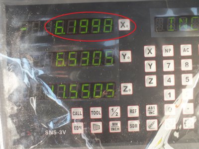
So….To start…I am very pleased with the quality of the ToAuto DRO !!! It is well made and heavy duty. Of course, time will prove the unit reliability….but…..good price, very large read out, many added computation features, accuracy @ 5um, metal cable runs between DRO and scales….All good….as far as I can see !! I purchased the scale sizes; 350mm, 450mm and 950mm. See attached pics !!
It took me some time to figure out the attachment pIan !! ….That was a challenge !! I used the 950mm scale on the X axis, the 450mm scale on the Y axis and the 350mm scale on the Z axis.
For the X and Z axis scales, sections of 1/4” x 3/4” Aluminum bar were used to attach the scales. I was successful in using ONLY existing bolt holes for all scale attachments. That was more luck than inspiration !!
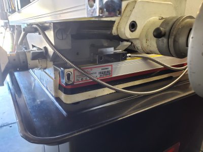
For the X axis….a long section of bar stock was attached to the ways. I attached the stock using the ways travel bolt limits blocks to attach to. The Ally bar bolted up tight the front facia of the ways. The Ally bar extended past the end of the Way (was equal to the width of the 950mm scale body) and the scale body was then attached to this bar. An additional short section of Ally bar stock was bolted to the location where the T shape way stop was originally located. This worked well because both Ally bars were then on the same vertical plane. The Scale head was then bolted to this shorter section. I should note that the scale body is above the scale head in this mounting.
For the Z axis, again a 1/4” x 3/4” Aluminum bar was used. A section of Ally bar stock was attached to two (2) existing threaded holes originally used to secure the Belt Speed Selection placard. The scale body was then attached to this bar. A Small Brass block was then machined ( L@1.25 “ x W@1.17” x H@0.50” with a 0.50” bore thru) and secured to the original vertical height indicator threaded rod. The scale head was then secured to this Brass block via a small Ally angle length.
Finally, the Y axis…..which was the most difficult….was the last to do. I used one of the two existing bolt holes used to lock the ways in the Y axis. I felt that the remaining lock bolt should be sufficient to lock the ways Y axis movement ( Seems to be). I machined a small Ally block ( L@1.64” x W@1.64” x H@1.01”) to act as a stand-off. This stand-off was bolted to the carriage via the existing bolt hole. A short section of Ally bar stock was then bolted to this stand-off block. The scale head was then attached to this short section ( see pics).
SO…I was wondering how to secure the scale body to the Mill base. I decided since there are four (4) bolts used to bolt the mill to its stand…..I would use the two (2) on the right side to secure the scale body. I machined an Ally angle stock to 1.3” x 2.0” x 20”. This angle stock was then secured to the JMD-15 unit base by removing the hold down bolts and capturing the angle and this then bolted the angle to the base. SO….the the Y axis scale base was then bolted to the angle stock front and back. All scale heads traveled straight and with ease.
As a final detail, the DRO readout unit was mounted to the existing Fwd/Rev/Off selector switch box stand-off bracket. Seemed like a good location that I could bolt the mounting bracket to. I may do some cable bundling….but…nothing other than that. Originally, I thought the cables were way to long. That is not the case.
SO…It is done !!!….and works perfect. Wow….What luck !! To anyone thinking about adding a DRO to their Jet mill….well….THIS is one way to do it !!! Challenging !!! ….But… I think a very worthwhile project !!! Face it….many beginners may start with a Jet Mill…. And a DRO is a great add-on !!!! The most difficult job is how to attach the scale body’s and scale head’s to the Mill !! I decided to share my adventure after a search of the Forum archives with no real specifics regarding a Jet Mill and DRO attachment. Hope this helps someone…sometime. CDBeam
Attachments
-
 ToAuto EB Pic.png250.9 KB · Views: 86
 -
 Y Axis install.jpg124.1 KB · Views: 90
 -
 Stand off components.jpg98.2 KB · Views: 68
 -
 Angle Bracket for Y Axis.jpg87.9 KB · Views: 62
 -
 X Axis install.jpg122.9 KB · Views: 90
 -
 Y Axis Stand off front.jpg80.3 KB · Views: 66
 -
 Y Axis Stand off back.jpg78 KB · Views: 71
 -
 Full Pic of the Jet @ DRO.jpg90.8 KB · Views: 99
 -
 Z Axis install.jpg100 KB · Views: 107
Last edited:


