- Joined
- Feb 1, 2015
- Messages
- 9,978
On March 19th, I replied to a thread begun by Cody Killgore entitled "Threading, Something Went Wrong Here" (post #19) where I show evidence of an problem with the threading dial on my Grizzly G0602. I had determined that the dial markings were not concentric with the gear shaft, creating an error of almost a half of a thread on the lead screw. This created the possibility of closing the half nuts one thread off on certain thread pitches which would have disastrous consequences for the thread being cut.
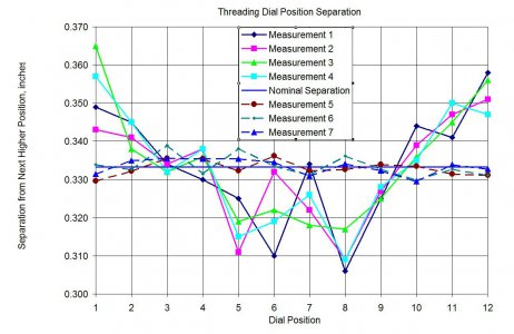
I had measured the carriage positions as each of the twelve threading dial marks lined up with the index mark and plotted out the difference between adjacent positions a the solid lines in the graph below. While there was variation in the readings, there was a clear sinusoidal pattern which would be predicted by eccentric dial markings.
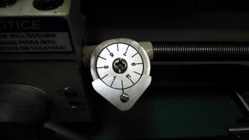
I designed a new dial, using SolidWorks and turned it on the lathe. The dial was engraved on the Tormach using a 45 degree carbide engraving tool. The stationary mark left a lot to be desired as well as it was hard to read and moved around easily so that was redesigned and machined on the Tormach. The engravings were filled with flat black enamel and the surfaces wet sanded with 400 grit sandpaper. The stationary plate has a dropped lip along the straight edges to prevent movement which is why it overhangs the threading dial housing.
The position measurements were repeated with the new dial shown as the broken lines in the graph. As can be seen, the sinusoidal variation has disappeared and the readability has improved as well, permitting visual positioning to better than +/- .005" maximum. This is accurate enough that the half nuts engage smoothly on all marks whereas before they would sometimes hang up due to mis-registration.
Bob


