- Joined
- Feb 15, 2020
- Messages
- 399
I've been using a Sherline 5400 mill for over a year now. Up untill now, aside from checking the tilt of the head with a test indicator, it's been used in "out of the box" condition.
A few weeks ago I was setting up to make a tapered part for a model engine. The size of the part and type of cut required the head set horizontal and the feed on the Y axis with the part held at an angle to the cutter.
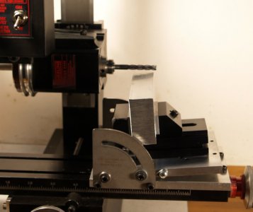
Rather than scrap the actual part I made a few test cuts. The first one looked like this. (staged photo)
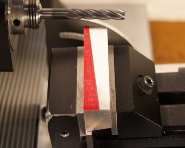
Sherline's instructions for the tilt table warn of this situation, but don't really explain why it happens or how to remedy it. They say that the angle plate must be mounted square to the table. What they mean is an imaginary line on the moving angle table must be parallel to the ways for the Y axis and perpendicular to the Z axis, not the table.
It took me about a week but I was able to figure out what was going on, figure out a solution, and finish the actual part. I ended up adding paper shims between the bottom plate of the angle attacment and the mill table.
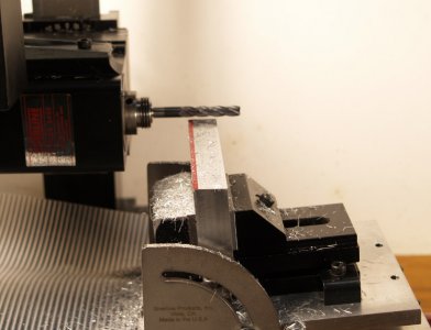
I recently purchased a Starrett precision square to properly check and align the machine and help me sort this out. Since I didn't have all the tools on hand, I never really read the alignment proceedures until now. That was almost as confusing as the problem above.
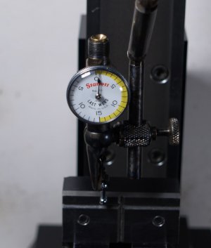
The first check, after assembling the machine and getting it close to square, is for built in error in the machine. They say it's usually .001" to .002" in 3" of travel. Here's what mine showed back to front.
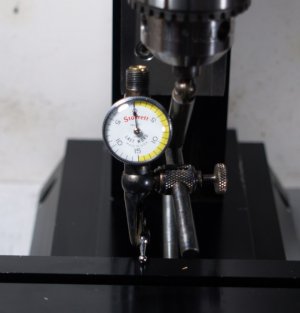
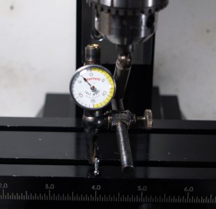
That's almost .003" in 2.75" of travel. I was a bit shocked by this, but it explains the results I've been getting in setups where the work was done on top of a part along the Y axis, like the part I was making above. It also explains why parts I've faced with the fly cutter were never quite square.
The directions say this error needs to be accounted for when making final squaring adjustment to the head. What I think that means is when you sweep the test indicator front to back (or back to front) during that alignment you should read this error.
So now your machine is indicated in and you're ready to go! Mount your vise to the table, indicate the fixed jaw square to X, clamp in your part, and ...
Everything you mount to the table is effected in some degree by the built in error. Unless you add some shims your vise won't be square to the Y or Z axes.
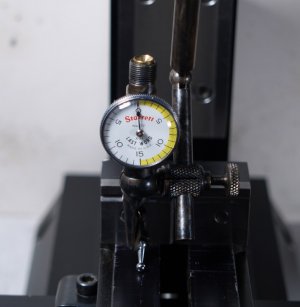
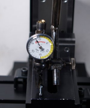
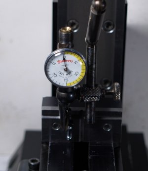
As all the errors build up it can get a bit frustrating. For most of what I've made over that past year the error was not really an issue. The parts work but were always just a bit off. I've been burning a lot of brain cells trying to sort out what I've been doing wrong. I figured it was just my inexperience. I think I'm going to put a sign up next to the machine or add a label to remind me of the error. That and buy some shim stock.
We'll see what happens when I go to square up the 2000 mill.
Eric
A few weeks ago I was setting up to make a tapered part for a model engine. The size of the part and type of cut required the head set horizontal and the feed on the Y axis with the part held at an angle to the cutter.

Rather than scrap the actual part I made a few test cuts. The first one looked like this. (staged photo)

Sherline's instructions for the tilt table warn of this situation, but don't really explain why it happens or how to remedy it. They say that the angle plate must be mounted square to the table. What they mean is an imaginary line on the moving angle table must be parallel to the ways for the Y axis and perpendicular to the Z axis, not the table.
It took me about a week but I was able to figure out what was going on, figure out a solution, and finish the actual part. I ended up adding paper shims between the bottom plate of the angle attacment and the mill table.

I recently purchased a Starrett precision square to properly check and align the machine and help me sort this out. Since I didn't have all the tools on hand, I never really read the alignment proceedures until now. That was almost as confusing as the problem above.
The first check, after assembling the machine and getting it close to square, is for built in error in the machine. They say it's usually .001" to .002" in 3" of travel. Here's what mine showed back to front.


That's almost .003" in 2.75" of travel. I was a bit shocked by this, but it explains the results I've been getting in setups where the work was done on top of a part along the Y axis, like the part I was making above. It also explains why parts I've faced with the fly cutter were never quite square.
The directions say this error needs to be accounted for when making final squaring adjustment to the head. What I think that means is when you sweep the test indicator front to back (or back to front) during that alignment you should read this error.
So now your machine is indicated in and you're ready to go! Mount your vise to the table, indicate the fixed jaw square to X, clamp in your part, and ...
Everything you mount to the table is effected in some degree by the built in error. Unless you add some shims your vise won't be square to the Y or Z axes.


As all the errors build up it can get a bit frustrating. For most of what I've made over that past year the error was not really an issue. The parts work but were always just a bit off. I've been burning a lot of brain cells trying to sort out what I've been doing wrong. I figured it was just my inexperience. I think I'm going to put a sign up next to the machine or add a label to remind me of the error. That and buy some shim stock.
We'll see what happens when I go to square up the 2000 mill.
Eric
