- Joined
- Oct 30, 2019
- Messages
- 225
This post continues into the first 2 replies due to per-post picture limits. All pictures are thumbnails but higher-resolution is available if you click the thumbnail.
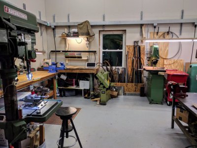
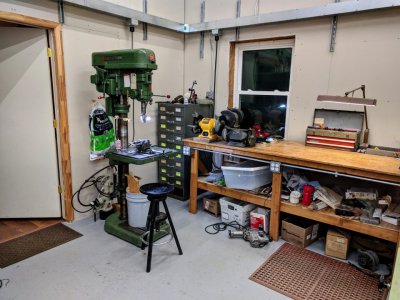
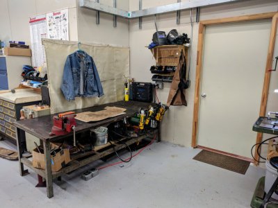
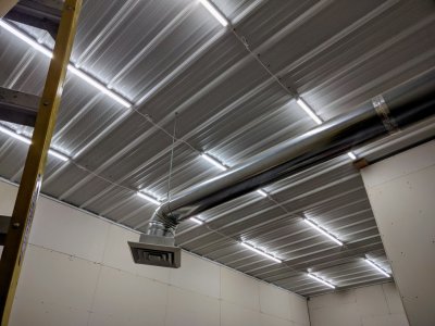
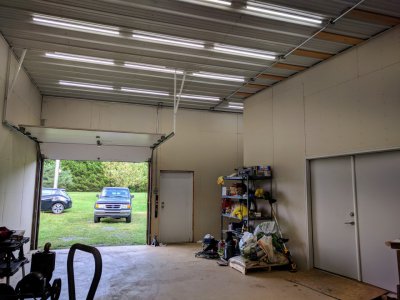
Our shop building was put in place by the previous owners of our house shortly after they purchased, around 2000-2001. The house is fairly small, and one of the coupleship was a musician -- teacher/instructor, performer with routine travels, some writing and recording at home, etc. They built the shop, a 48x60 pole barn, with the intention of finishing a substantial portion of the footprint as a music studio and office space.
You can see my other thread at https://www.hobby-machinist.com/threads/set-up-a-wood-shop-h-m-sacrilege.97651/ regarding building a woodshop in part of the space that they had finished for office and music-oriented use.
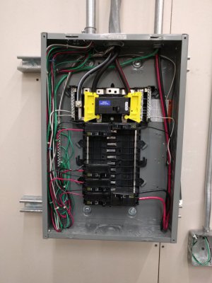
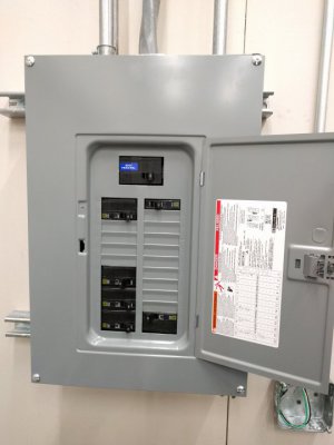
In general, the building was lacking in electrical infrastructure. Facts:
The more important facts...
The initial goals of the electrical upgrade project, which I had roughly sketched out with a floorplan of the building:
Those are the general goals. There were more ideas, and changes along the way - which will be explained as we go through the project below.
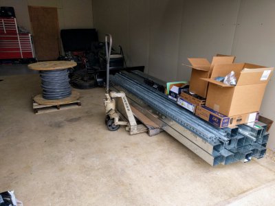
To start, I estimated the length and quantity of major materials needed. Specifically, things I knew I could not just pop out and buy in retail; or things I could buy in bulk now to save effort and/or money:
This first (only) delivery was about $2500 from a local electrical supply house
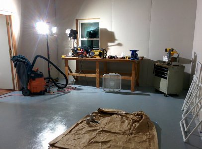
Around the time this was all delivered, we had just finished building the woodshop space. The electrical requirements in here were simple and along a single wall. This seemed like a good space to prototype the unistrut approach as well as the wire trough, and it also did not depend on either of the subpanels being installed.
So above I mentioned conduit being used. While plenty of conduit is used, the main runs in each room are in 4x4 wireway. This is for a number of reasons:
Locally, wireway ended up costing $55 per 10ft stick. Cheaper than I originally expected this to be, which helped sway the decision as well.
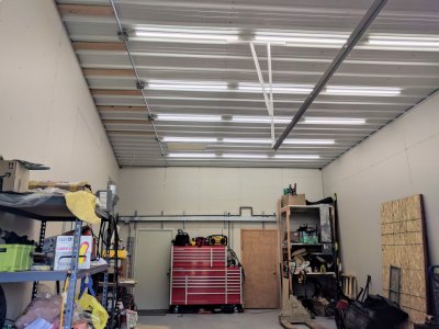
I ordered enough to use on most walls in the back shop; 1 or 2 walls in the woodshop, the back wall of the garage, and maybe a few other small areas.
Ok so back to the woodshop...
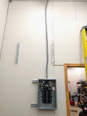
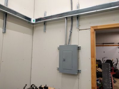
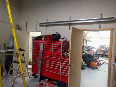
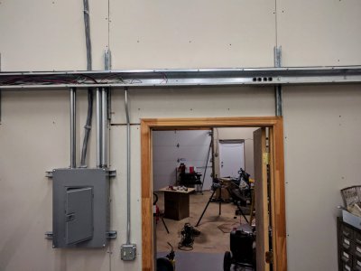
On the longest wall of the woodshop, which is near the building's main panel, I placed 20" pieces of unistrut on every 3rd stud - giving 4' spacing. This would give 2-3 points of support per stick of wireway.
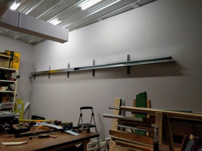
There were two challenges solved during installation of the unistrut and wireway:
- The interior walls of the building use sheet metal studs. How do you attach to these meaningfully?
- How can I hang 10' sticks of wireway by myself, to avoid needing to bring my wife in every 15-30 minutes throughout portions of the project?
For the studs, the solution is to place toggle bolts in the exact center of the stud so that it can expand within the cavity of the stud. Between a studfinder (for coarse location), and exploratory drilling with a 1/16" drill bit (for precise location), it was easy enough to locate the center of the stud, within 1/8". Drilling a 9/16 hole and dropping 3x 3/16 toggle bolts for each 20" piece of unistrut -- this seemed plenty strong for hanging the wireway plus future compressed air and dust collection lines.
For hanging wireway by myself, I found that I could use some longer 3/8 bolts and large washers to place temporary "studs" that would hold the wireway. This would allow me to adjust the wireway vertically to level it; and then mark and drill for holes to place the bolts and spring nuts that would permanently fasten it to the unistrut.
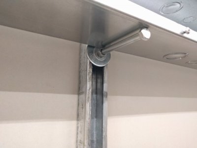
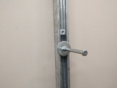
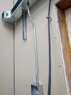
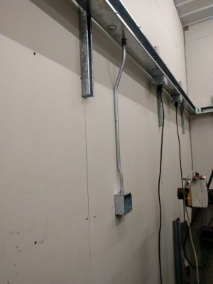
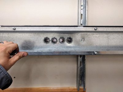
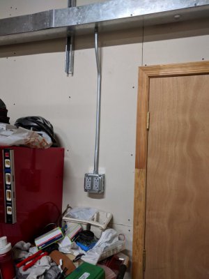
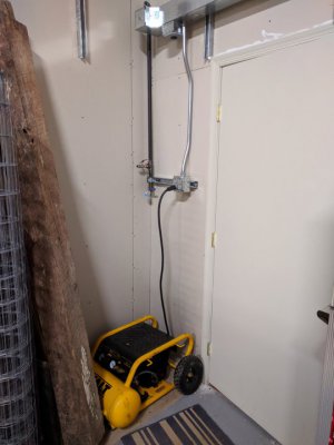
In the wood shop I had an additional challenge to overcome about how to have the conduit drops leave the back of the wireway to extend downwards. This is desirable in the woodshop because I wanted to keep space open on the unistrut, below the wireway, for future dust collection to be hung on the same wireway. I used some tight-radius 90deg elbow fittings that were terrible to pull wire through -- I'm glad I only needed to do 3 of these, and would not deploy more.
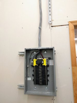
The wireway in the woodshop is fed directly from the main panel, via 1" EMT conduit along the ceiling. This allows some room for fishing future conductors in case new circuits are needed for equipment over time.
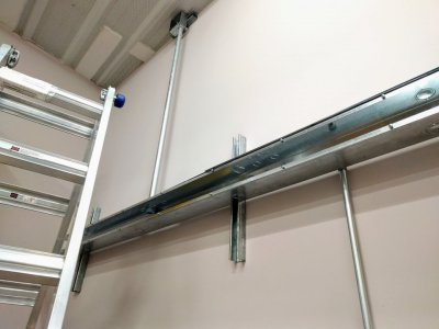
At this point I was loving the space and versatility of the wireway, and had dialed in my installation processes that would be used elsewhere in the building
My pigtails were a bit long for junctions, but with the extra space in the wireway I did not hesitate to make things easier for my future self.
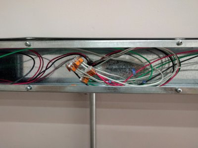
Woodshop done for now, it successfully provided the proof-of-concept for how we would mount the wireway on unistrut in the other shop.
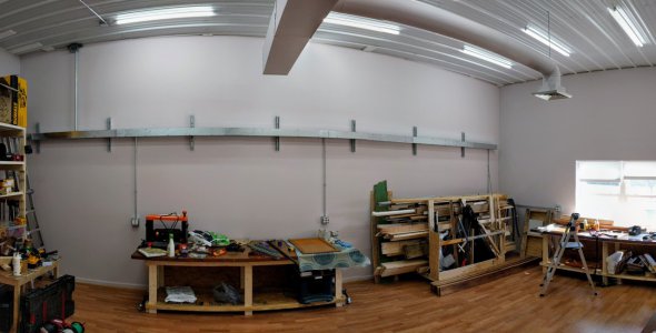
Time to start hanging unistrut in the back shop.
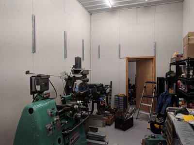
Thanks to having the unistrut+wireway solution ironed out in the woodshop, pretty quickly I was at a point where I wanted to hang the unistrut and subpanel. However, this depended on running the feed from the main panel, so I could place the subpanel and not have to fight to route the wire behind the wireway.
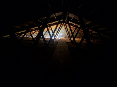
This is where we get into a side project. You see, this building is a 48x60 pole barn with a truss roof. The roof trusses are on 10' centers, with 2x6 stringers run between the bottom chords of the trusses. Even if I was a taller person, there is no way to walk around safely in the attic on that 4x10ft framework. Additionally, there is nothing to grab onto overhead - the peak of the roof is 8 to 10 feet above the truss chords.
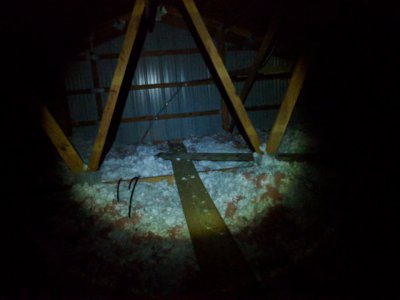
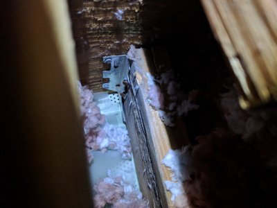
The 2x6 stringers attach inside of the truss lower chords
So we need to build a walkway. However, the access to the attic is over the garage and is only approximately 20x30 inches in size.
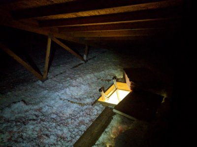
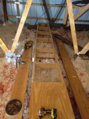
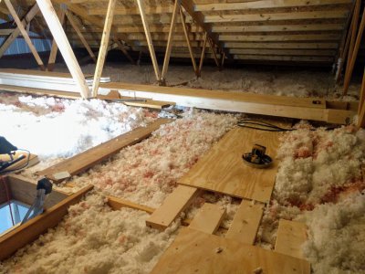
Downstairs, I prototyped a section of walkway that could run down the middle of the attic (under the peak of the roof), and sit on top of the lower truss chords. 10' long sections, joined together rigidly, forming one long 60' walkway down the center of the attic. Each section is two 2x6x10 on edges, with 1/2 sheets of plywood screwed to the top and some additional stringers screwed in to strengthen under the plywood.
All of this was cut to length downstairs, brought up in pieces, and assembled in the attic. The assembled sections were just too heavy to bring up a ladder and maneuver into the attic.
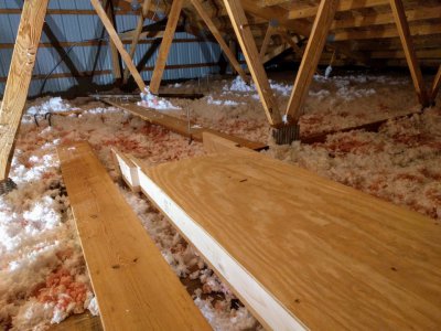
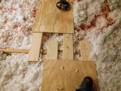
To gain access from the center out towards the eves, I put pairs of 2x6x10s on their side, with a half sheet of plywood. These formed portable planks with the 2x6es protruding from the end, so that two abutting ones can overlap each other on top of a stringer.
Our shop building was put in place by the previous owners of our house shortly after they purchased, around 2000-2001. The house is fairly small, and one of the coupleship was a musician -- teacher/instructor, performer with routine travels, some writing and recording at home, etc. They built the shop, a 48x60 pole barn, with the intention of finishing a substantial portion of the footprint as a music studio and office space.
You can see my other thread at https://www.hobby-machinist.com/threads/set-up-a-wood-shop-h-m-sacrilege.97651/ regarding building a woodshop in part of the space that they had finished for office and music-oriented use.
In general, the building was lacking in electrical infrastructure. Facts:
- The building has its own 200A split-phase meter/service
- The main panel is in the garage
- The only outlet in the garage was a duplex outlet right next to the panel, 4' off the ground
- In the garage (roughly 20x30), there were only 2 fluorescent fixtures (13' ceiling), insufficient lighting for a garage
- There were no outlets on the exterior of the building
- In the semi-finished hallway there are 2 strings of duplex outlets on 15a breakers, fed by the main panel via 12/2 romex along the ceiling
- Reasonable fluorescent lighting in the hallway
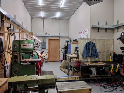
- Insufficient lighting in the finished space (where the woodshop was built) - 2 fluorescent fixtures for a 40x25 ft room
The more important facts...
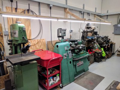
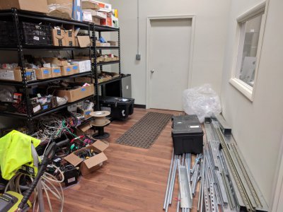
- In the back room which I was setting up as the metal shop, there were zero outlets and zero lights
- I had been surviving with my workbench which had a small task light and some outlets mounted on it
- The bench was in turn fed via SO cable from an outlet in the hallway
- Some overhead lights I mounted were just plugged into the bench when I wanted them
- Everything else in the room plugged into the bench

The initial goals of the electrical upgrade project, which I had roughly sketched out with a floorplan of the building:
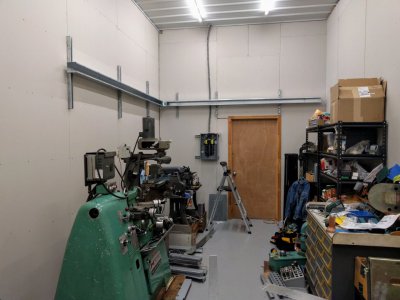
- Install a 100A subpanel in the back/metal shop for mechanical/noisy electrical loads in that room and the back wall of the garage
- Design a conduit system that is versatile for future expansions/changes, as machinery and benches are added or moved around
- Conduit/etc should be mounted above the doors and windows, to allow for straight/easy wire pulls. Ideally step-stool height instead of 6-12ft ladder height for access/work
- Mount the main overhead conduit/wireway on unistrut that can be used to mount other systems such as compressed air
- General-purpose quad boxes on GFCI
- L14-20 twist-lock receptacles for bench- and wall-mounted power strips, so that 120v and 240v are both available; and benches/strips can be moved
- Improve lighting everywhere
- Additional enhancements for computer equipment, including another 100A subpanel to keep computer hardware from seeing voltage drop that would be seen if the metal shop subpanel was shared (with possible high load/inrush currents, etc)
- Everything safe and to code.
Those are the general goals. There were more ideas, and changes along the way - which will be explained as we go through the project below.
To start, I estimated the length and quantity of major materials needed. Specifically, things I knew I could not just pop out and buy in retail; or things I could buy in bulk now to save effort and/or money:
- 170ft of 4x4 wireway/wire trough (17x 10ft sticks), and couplers/elbows for the same
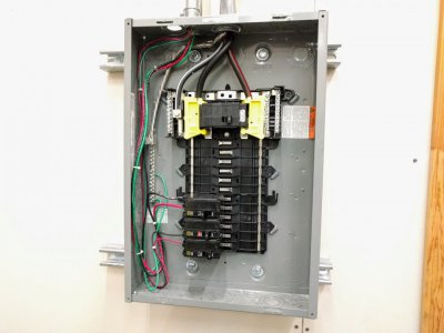
- 2 Square D QO 100A main-breaker subpanels; with ground bars and covers for the same. One panel for the metal shop covered in this post, another panel for computer/resistive loads later on.
- 100A breakers for the main panel (also a QO panel)
- Various single-pole and double-pole breakers for the circuits I anticipated installing
- A bundle each of 1/2 and 3/4 EMT conduit; bundle of unistrut
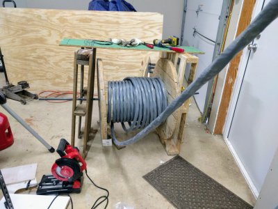
- 175ft of 2/0, 2/0, 2/0, 1awg Al SER cable for the subpanel feeds
- A case each of Raco 4" square junction boxes and outlet boxes (with 1/2 and 3/4 knockouts)
This first (only) delivery was about $2500 from a local electrical supply house

Around the time this was all delivered, we had just finished building the woodshop space. The electrical requirements in here were simple and along a single wall. This seemed like a good space to prototype the unistrut approach as well as the wire trough, and it also did not depend on either of the subpanels being installed.
So above I mentioned conduit being used. While plenty of conduit is used, the main runs in each room are in 4x4 wireway. This is for a number of reasons:
- Versatility. This is easier to make changes in over time, without worrying about conduit or junction boxes filling up.
- Similarly, I can just punch new holes whenever I want to drop a new conduit run or junction box out of it
- In a large conduit system, effectively all your junction boxes along the main trunk/path need to be determined on day one. There is no chance to splice a box into the pipe system later on, without pulling all the existing conducors back. Wireway does not have this problem.
- For equipment that uses twistlock connectors, those can be mounted directly under the wireway instead of needing to figure out a nice way to have them hang from a junction box (without undue strain on the connector protruding 90 degrees from the wall)
- Even oversizing conduit... in the metal shop, a 1" conduit could easily fill up when you are talking about 6awg or 8awg conductors for welder outlets, etc. Not to mention having to consider code inputs on conduit fill/sizing, derate conductors as you add more current-carrying conductors, etc. Wireway does not have this problem without insane numbers of conductors being present
Locally, wireway ended up costing $55 per 10ft stick. Cheaper than I originally expected this to be, which helped sway the decision as well.
I ordered enough to use on most walls in the back shop; 1 or 2 walls in the woodshop, the back wall of the garage, and maybe a few other small areas.
Ok so back to the woodshop...
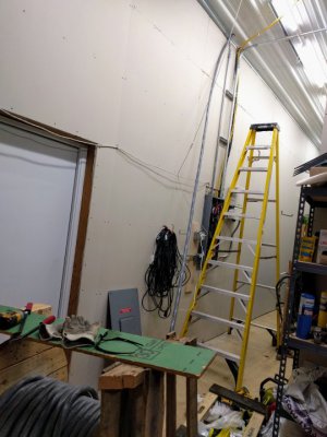
On the longest wall of the woodshop, which is near the building's main panel, I placed 20" pieces of unistrut on every 3rd stud - giving 4' spacing. This would give 2-3 points of support per stick of wireway.

There were two challenges solved during installation of the unistrut and wireway:
- The interior walls of the building use sheet metal studs. How do you attach to these meaningfully?
- How can I hang 10' sticks of wireway by myself, to avoid needing to bring my wife in every 15-30 minutes throughout portions of the project?
For the studs, the solution is to place toggle bolts in the exact center of the stud so that it can expand within the cavity of the stud. Between a studfinder (for coarse location), and exploratory drilling with a 1/16" drill bit (for precise location), it was easy enough to locate the center of the stud, within 1/8". Drilling a 9/16 hole and dropping 3x 3/16 toggle bolts for each 20" piece of unistrut -- this seemed plenty strong for hanging the wireway plus future compressed air and dust collection lines.
For hanging wireway by myself, I found that I could use some longer 3/8 bolts and large washers to place temporary "studs" that would hold the wireway. This would allow me to adjust the wireway vertically to level it; and then mark and drill for holes to place the bolts and spring nuts that would permanently fasten it to the unistrut.


In the wood shop I had an additional challenge to overcome about how to have the conduit drops leave the back of the wireway to extend downwards. This is desirable in the woodshop because I wanted to keep space open on the unistrut, below the wireway, for future dust collection to be hung on the same wireway. I used some tight-radius 90deg elbow fittings that were terrible to pull wire through -- I'm glad I only needed to do 3 of these, and would not deploy more.
The wireway in the woodshop is fed directly from the main panel, via 1" EMT conduit along the ceiling. This allows some room for fishing future conductors in case new circuits are needed for equipment over time.

At this point I was loving the space and versatility of the wireway, and had dialed in my installation processes that would be used elsewhere in the building
My pigtails were a bit long for junctions, but with the extra space in the wireway I did not hesitate to make things easier for my future self.

Woodshop done for now, it successfully provided the proof-of-concept for how we would mount the wireway on unistrut in the other shop.

Time to start hanging unistrut in the back shop.

Thanks to having the unistrut+wireway solution ironed out in the woodshop, pretty quickly I was at a point where I wanted to hang the unistrut and subpanel. However, this depended on running the feed from the main panel, so I could place the subpanel and not have to fight to route the wire behind the wireway.
This is where we get into a side project. You see, this building is a 48x60 pole barn with a truss roof. The roof trusses are on 10' centers, with 2x6 stringers run between the bottom chords of the trusses. Even if I was a taller person, there is no way to walk around safely in the attic on that 4x10ft framework. Additionally, there is nothing to grab onto overhead - the peak of the roof is 8 to 10 feet above the truss chords.

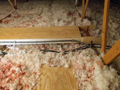
The 2x6 stringers attach inside of the truss lower chords

So we need to build a walkway. However, the access to the attic is over the garage and is only approximately 20x30 inches in size.

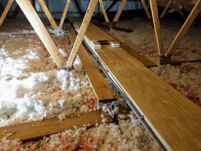
Downstairs, I prototyped a section of walkway that could run down the middle of the attic (under the peak of the roof), and sit on top of the lower truss chords. 10' long sections, joined together rigidly, forming one long 60' walkway down the center of the attic. Each section is two 2x6x10 on edges, with 1/2 sheets of plywood screwed to the top and some additional stringers screwed in to strengthen under the plywood.
All of this was cut to length downstairs, brought up in pieces, and assembled in the attic. The assembled sections were just too heavy to bring up a ladder and maneuver into the attic.


To gain access from the center out towards the eves, I put pairs of 2x6x10s on their side, with a half sheet of plywood. These formed portable planks with the 2x6es protruding from the end, so that two abutting ones can overlap each other on top of a stringer.


Last edited:

