Table drive cone pulley

Jubil

H-M Supporter - Sustaining Member
H-M Platinum Supporter
Joined
Apr 13, 2016
Messages
341
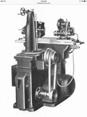
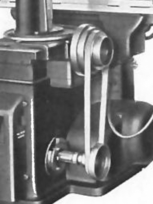
I am refurbing a B&S #13 universal grinder, built around 1940. It has a flat belt cone pulley system to drive the table. The lower cone pulley is missing. I have searched internet and manuals for the pulley sizes, haven't been able to find it. I found a pic in a manual but it doesn't give sizes.
If no one knows the sizes, maybe someone can tell me how to calculate them from the parts I have. I have upper cone pulley, and the belt that parts manual listed and of course the center to center distances.
I have a Machinery's Handbook but I can't seem to find what I need. It tells pulley sizes for rpm, belt length needed etc.
Any help will be much appreciated.
Thanks
Chuck
 
Most flat belt systems I've seen the pulleys are the same size. Folks have made them out of wood, aluminum, steel, whatever. If you're not trying to restore to factory you could use a single pulley on a 3-phase motor with a VFD.

John
 
Most flat belt systems I've seen the pulleys are the same size. Folks have made them out of wood, aluminum, steel, whatever. If you're not trying to restore to factory you could use a single pulley on a 3-phase motor with a VFD.

John

Thanks for reply. I thought they would be the same size too but not so on this one. The one in pic has largest pulley about the same size as smallest on upper pulley. And I am trying to restore at least close to original.
Chuck
 
Depending on the quality and/or clarity of the photo in your manual, you may be able to scale the unknown dimensions off of the known pulley sizes you have. For example, you measure one or more of the pullies in the photograph of which you have physical examples and then compare the relationship of the unknown pullies in the photograph to those. With a pair of dividers and a bit of math, one can often get quite close.

I do this frequently when faced with having to reproduce no longer extant features on historic architecture and landscapes. There is always something in an image that you can apply a real-life size to, and from that you can then derive other elements in the same picture by their relationship to the known.

Post a copy of the image in your manual here if you like, it may be possible to get a good idea from what you already have.

-frank
 
Don't know if this is the photo that you have, Chuck, but if it is I make the largest of the lower pullies 1.25 times the diameter of the smallest upper pulley. So, if your smallest upper pulley diameter was to measure "N" inches multiply "N" x 1.25 and that should be pretty close to the diameter of the largest of the lower pullies.

image.pngimage.png

It looks to me like the belt length stays fixed for all four pulley steps (ie: the pulley centre to centre spacing stays fixed) so the other unknown diameters on the lower can be figured based off the belt circumference needed for the outside pair. Gates Belts has a nifty online or phone app calculator to make that part easy if you know two of the three variables (pulley A, pulley B, and centre to centre distance).

Hope that gives you something to play with. Of course the best would be if somebody happened to have the pulley sizes!

-frank
 
Don't know if this is the photo that you have, Chuck, but if it is I make the largest of the lower pullies 1.25 times the diameter of the smallest upper pulley. So, if your smallest upper pulley diameter was to measure "N" inches multiply "N" x 1.25 and that should be pretty close to the diameter of the largest of the lower pullies.

View attachment 300771View attachment 300772

It looks to me like the belt length stays fixed for all four pulley steps (ie: the pulley centre to centre spacing stays fixed) so the other unknown diameters on the lower can be figured based off the belt circumference needed for the outside pair. Gates Belts has a nifty online or phone app calculator to make that part easy if you know two of the three variables (pulley A, pulley B, and centre to centre distance).

Hope that gives you something to play with. Of course the best would be if somebody happened to have the pulley sizes!

-frank

Yep, that's the pic I have. When I go out to the shop today I will have something to go on at least. Thanks
Chuck
 
Also, math.

It’s very likely the original designers had specific rates of travel in mind when they built it. If you can find those you can work backwards to the speeds needed and drive ratios required.
 
Back
Top