- Joined
- Dec 24, 2020
- Messages
- 1,055
Hi all,
I did a few searches and couldn't come up with anything, so I'm starting a new topic...hopefully in the correct location.
For background, I'm just a hobbyist plugging away in the shop learning how to turn good stock into scrap while burning up all my play money, so this isn't a critical matter.
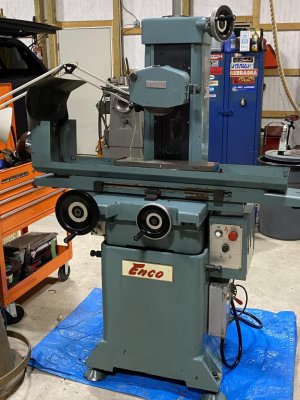
I just bought an Enco branded 6x18 surface grinder that seems to be in pretty good condition. I've done some reading and some folks suggest maybe they were made by Harig, but others have said they were a copy made in Taiwan....the manual is clearly an imported product. Regardless of all of that, I got it cheap...like really cheap. The motor powers up, the spindle is quiet, everything moves smoothly, the lube system seems to work and it cleaned up really nicely with just some Simple Green and shop towels. The data plate says 1986, so it's been around a while, but I honestly don't think it saw much work...came out of a very small shop.
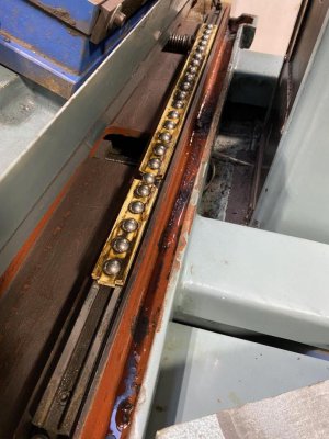
The one thing I noted was that when I went to float the table for transport I saw the ball retainers had some damage and one missing section of 5 balls from both front and back ways. Other than being in sections, rather than one long retainer, this looks like the same setup as a Harig. The table seems to move smoothly and I might be able to run it this way just fine, but thought I'd explore a fix and want a sanity check on my idea.
I'm sure the original ball retainers aren't available since Enco got swallowed up by the parent company MSC and even then, it's a 34 year old import machine...not likely finding parts. A check on Harig ball retainers that look similar showed them at nearly $200 each.
I can get the correct size acetal/Delrin easily enough, so I'm wondering if I can't make replacements. If I simply drilled holes carefully, sized for new 5/8" ball bearings like the originals, I can't see why they wouldn't work, or am I missing something? There shouldn't really be any weight on, or significant contact with the ball retainer so they should just keep the balls from escaping and spaced properly....unless I'm totally confused. It would seem even a slightly loose fit between the ball and ball retainer shouldn't really hurt anything other than creating a place to trap debris and cause wear but the only contact should be the balls and the ways, right?
It would seem that keeping the line of balls straight would be the most critical factor, so I was thinking of mounting it to the Bridgeport table (retainers are only about 30" long) and drilling the holes with the mill so it's just a matter of traversing the table to the next spot.
If there's a better way to go about this, or if I'm totally off base don't hesitate to let me know...won't hurt my feelings one bit!
Here's a pic of the grinder after 30 minutes with Simple Green and shop towels, and the ball retainers as I found them:
I did a few searches and couldn't come up with anything, so I'm starting a new topic...hopefully in the correct location.
For background, I'm just a hobbyist plugging away in the shop learning how to turn good stock into scrap while burning up all my play money, so this isn't a critical matter.
I just bought an Enco branded 6x18 surface grinder that seems to be in pretty good condition. I've done some reading and some folks suggest maybe they were made by Harig, but others have said they were a copy made in Taiwan....the manual is clearly an imported product. Regardless of all of that, I got it cheap...like really cheap. The motor powers up, the spindle is quiet, everything moves smoothly, the lube system seems to work and it cleaned up really nicely with just some Simple Green and shop towels. The data plate says 1986, so it's been around a while, but I honestly don't think it saw much work...came out of a very small shop.
The one thing I noted was that when I went to float the table for transport I saw the ball retainers had some damage and one missing section of 5 balls from both front and back ways. Other than being in sections, rather than one long retainer, this looks like the same setup as a Harig. The table seems to move smoothly and I might be able to run it this way just fine, but thought I'd explore a fix and want a sanity check on my idea.
I'm sure the original ball retainers aren't available since Enco got swallowed up by the parent company MSC and even then, it's a 34 year old import machine...not likely finding parts. A check on Harig ball retainers that look similar showed them at nearly $200 each.
I can get the correct size acetal/Delrin easily enough, so I'm wondering if I can't make replacements. If I simply drilled holes carefully, sized for new 5/8" ball bearings like the originals, I can't see why they wouldn't work, or am I missing something? There shouldn't really be any weight on, or significant contact with the ball retainer so they should just keep the balls from escaping and spaced properly....unless I'm totally confused. It would seem even a slightly loose fit between the ball and ball retainer shouldn't really hurt anything other than creating a place to trap debris and cause wear but the only contact should be the balls and the ways, right?
It would seem that keeping the line of balls straight would be the most critical factor, so I was thinking of mounting it to the Bridgeport table (retainers are only about 30" long) and drilling the holes with the mill so it's just a matter of traversing the table to the next spot.
If there's a better way to go about this, or if I'm totally off base don't hesitate to let me know...won't hurt my feelings one bit!
Here's a pic of the grinder after 30 minutes with Simple Green and shop towels, and the ball retainers as I found them: