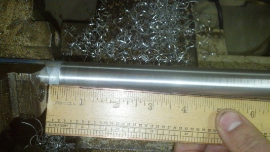
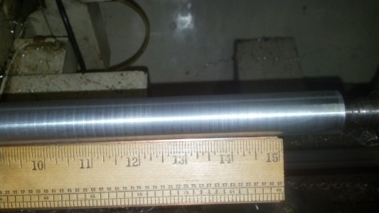
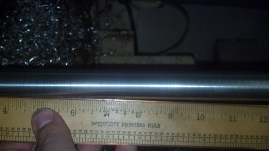
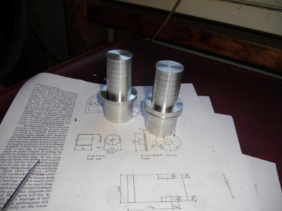
I'm just getting familiar with my CNC-converted South Bend "Fourteen" 14x40 lathe. I'm having some strange issues with surface finish. It's not that the the finish isn't smooth, but there are regular waves in it. Basically the diameter of a finished part wanders in and out .001"-.002" every 1/4" of length or so. It's most exaggerated on a high-rake cutter (like for aluminum). I've included a picture of a pair of aluminum parts I turned (about 1" OD) with a nice CCGT high-rake aluminum insert. It left a smooth finish, but you can see the color striations which correspond to a diameter variance. The dark bands are lower diameter, about .001"-.002" smaller (diametral) than the light bands. Even another light pass yielded the same pattern. I only recently acquired this machine and most of the converting and setup work was already done. I've written the previous owner and he never encountered this before, so it's likely something that happened during the move or setup at my house.
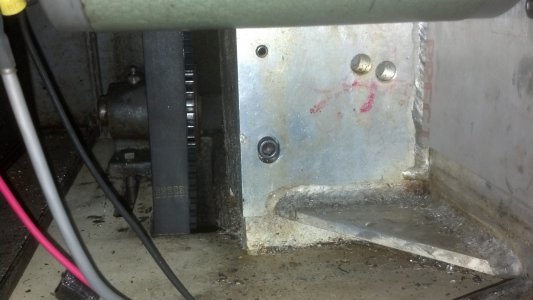
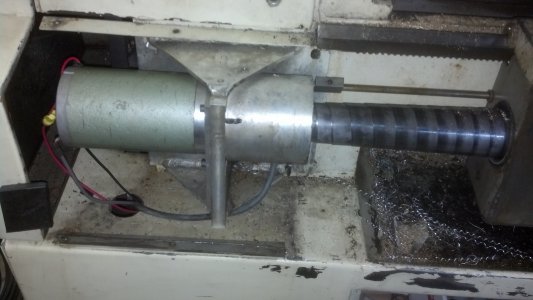
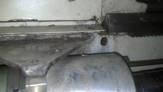
Last night I had had enough and I took the lathe partially apart to investigate this. It seems to be something to do with the leadscrew, leadscrew bearing, or leadscrew ballnut. The striations turn out to be the same pitch as the leadscrew. It turns out that if I loosen up all the bolts that hold the headstock-end leadscrew support bearing in place the striations go away. This leads to other problems, however, so I can't run it that way. I cut a few inches of test bar (aluminum) while tightening and loosening those bearing screws and you could actually see the problem start and stop. Tightening the upper screws on the bearing support make it worst. I believe that every revolution the leadscrew is applying slight upward pressure on the saddle. That's why it makes no difference what the feedrate is. It's a mechanical issue. I've temporarily reached a happy medium with the bearing support screws just snugged (and one of them removed entirely) and the lathe is cutting a mostly un-noticeable pattern that I can polish out.
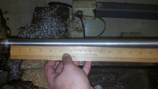
It seems to me that there are a couple possible causes for this. I can't really tear the lathe down until I'm done with the current project (a Christmas present) but for now I'm bouncing ideas around. I thought that one of the three bearings in the leadscrew system had to float? You can't build it aligned well enough to run 3 fixed bearings, right? Does anyone know if it's the left support bearing that is typically supposed to float, or is it the ball nut that's supposed to float? It could be that whichever bearing is supposed to float has stopped floating; possibly gotten a big chip lodged in it or a little surface rust. I thought that the ballnut was supposed to be the one that floated axially to isolate the saddle from the leadscrew system? Unfortunately the more likely culprit is a bent leadscrew, probably during moving the lathe, that is exceeding the axial float limitations of the system.
I can't quite figure out how the leadscrew comes apart on this lathe. I looked at it last night and it has me a bit stumped. The servo motor comes off readily (I had it off last night) but I can't figure out how the left side bearing carrier comes apart. It looks like I have to drop the leadscrew, apron, and both bearing carriers off in a lump and then take it apart after that. A job that big will have to wait until after Christmas for sure. The leadscrew is driven by a nice poly coupler, BTW, and I didn't see anything wrong with it so that doesn't appear to be the problem.


