Stepconf setup info for ST-V2 BoB

devils4ever

H-M Supporter - Gold Member
H-M Supporter Gold Member
Joined
May 13, 2019
Messages
1,016
As the title states, I'm trying to configure LinuxCNC using stepconf for a ST-V2 break out board. I'm trying to follow the wiring diagram in the manual for the ST-V BoB.

I think I have the pins setup up properly for the X, Y, and Z-axis for pulse and direction:
X-pulse: 2
X-direction: 3
Y-pulse: 4
Y-direction: 5
Z-pulse: 6
Z-direction: 7

I'm using E-stopin with pin 10. I assume this needs to be set active low.

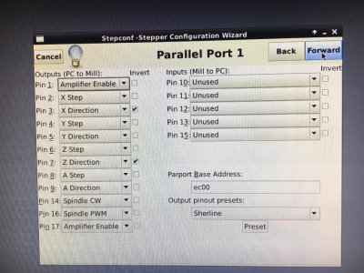
I'm having trouble on how to set the Enable pin to 14. Which selection in stepconf should I use?

Thanks.
 
I just dug out my CNC project after moving but I believe I have the correct configuration for you. If you're still struggling tomorrow morning hit me up and I'll start up the PC and let you know how mine is configured.

John
 
Yes, that would be greatly appreciated. I don't have the motor controllers or motors yet, only the BoB. They are due in today or tomorrow. I'm trying to get this setup up before they get here.

I'm thinking of using Amplifier Enable for this? Or, Spindle CW?

A few more questions.

Also, I'm using a separate USB power supply instead of using the PC's USB port for isolation. Is this correct?

And I'm using a separate 12V power supply which I think is used only for the switches? In my case, this would be the E-stopin.

As far as driver timing settings: I'm leaving them set to 5000 ns for Step Time and Step Space and 20000 ns for Direction Hold and Direction Setup.

A schematic of the ST-V2 breakout board would be great. I wish they would publish it. It would make life easier.
 
Great. Thanks.

So, are you using Amplifier Enable on pin 1 as the motor controller enable?
 
Great. Thanks.

So, are you using Amplifier Enable on pin 1 as the motor controller enable?
I use Amplifier Enable to enable my servos. It enables them as soon as the machine is powered on by the LinuxCNC software.

Also, as a note, you don't need to use the same pins as the ones they reference in the manual. The only thing that matters is that you use output pins for outputs and input pins for inputs.
 
Thanks!

I'm just was uncertain what Amplifier Enable, Spindle CW, Spindle PWM even mean!
 
Thanks!

I'm just was uncertain what Amplifier Enable, Spindle CW, Spindle PWM even mean!
Amplifier enable sends an enable signal to your drives. Some stepper drivers need enable signals, some will default to enable without the enable signal so they aren't necessarily needed.

Spindle CW is Spindle Clockwise. That pin will be activated when you start your spindle in the clockwise direction. There is also spindle CCW which will activate when you want to turn the spindle counter clockwise (If it goes that way). You could use that for rigid tapping if you have a spindle encoder. Spindle PWM is the pin that will be used to handle speed control on your spindle. There is one pin specifically noted on the breakout board for PWM output (Pulse width modulation if you aren't familiar) and it uses a duty cycle to create an average voltage signal. Ie if you are referencing 10v for spindle speed control, a 40% duty cycle (40% on 60% off) will average a 4v signal and your spindle drive should go to 40% speed in either CW or CCW depending on which pin is activated.
 
I don't plan on connecting anything to the spindle. I figure I can manually turn on and off the spindle motor and set the speed.

Is there any drawbacks to doing it this way?
 
I don't plan on connecting anything to the spindle. I figure I can manually turn on and off the spindle motor and set the speed.

Is there any drawbacks to doing it this way?
There is nothing wrong with doing it that way. I did that for a while before getting a servo to drive the spindle which was easier to control.

There are a few drawbacks to it, but nothing to lose sleep over. There are times that it is convenient to be able to change the spindle speed during the program. An example is running the spindle slower while roughing to keep the motor in the ideal torque range, then speeding up to finish with the higher surface speed. It also requires you to know the correct speed for every operation. It could slow you down if you are running a part using 10+ tools. If you leave it running unattended, the spindle will run continuously until you return.

It is far from the end of the world, but having the computer control the spindle is certainly more convenient.
 
Back
Top