- Joined
- Nov 23, 2014
- Messages
- 2,632
POTD was repairing some Erector set parts for sale on eBay. One thing leads to another; I needed some springs and could have gone the finished product route, or wind them myself. I’ve had making a spring-winding jig on my “list of good intentions” for 30+ years. Finally got around to it!
I made the main body out of a 5/8” aluminum rod. The tip is from my Hobart MIG-welder. I happened to grab a 0.030” hole tip as my springs would be made from 0.020” music wire. Naturally, if I wind some larger springs, the tip will need to be drilled out.
My plan was to hold the jig in a QCTP tool holder. The front two set screws would clamp the jig in place, one of the back ones would be used to put a drag on the music wire. The wire needs to be under tension as it wraps on a mandrel, otherwise the coil size will not be consistent (too loosely wrapped around the mandrel).
Started by making a pass on the bottom side of the aluminum with an end mill. This would give a flat surface for mounting in the QCTP tool holder. Then flipped it and hogged out an area for the tension screw.
The 5/16" deep pocket was milled in the 5/8" rod with a 1/2" end mill. I had some 1/8" aluminum plates on either side of the round to spare my vise jaws.
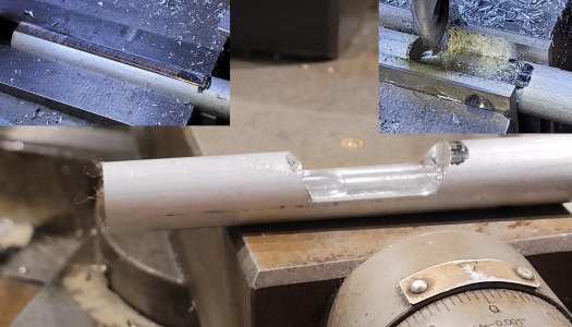
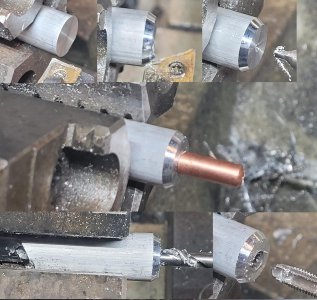
Then over to the lathe to drill/tap the ¼”-28 threaded hole for the MIG welder tip. I ran the tap drill just through the solid rod and into the hogged-out area for the tension screw by 1/8” (though not super critical). I didn’t want to go real deep with the tap drill as the flat surface in the hogged-out area is where the music wire will be clamped to. If I went too deep with the drill, the clamping surface would be trough larger than the wire; no clamping force at that point.
Face, chamfer, center drill, tap drill and thread a 1/4"-28 hole.
Then back to the mill to add a tapered area behind the hogged-out area for wire feed clearance. Then ran a drill mill down the center of the clamping area about 0.005" deep to give the wire a small trough to run in. I used a ¼” roughing end mill to cut a slot at the very rear of the fixture for securing the music wire spool. Also milled a shallow trough in the top of the fixture from the spool to the tapered area to give the wire a place to run. Flipped the fixture to hog out a taper on the bottom of the wire spool area to give some clearance to the lead-top edge of the spool. Then drilled/tapped a 6-32 hole at the end for an axle for the music wire spool.
The round was oriented by setting the flat milled on the bottom on a square (though this wasn't super critical)
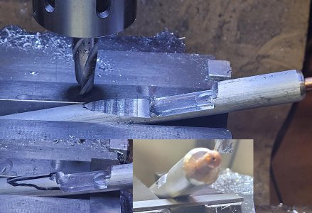
Milled a pocket at the back for the spool of wire. Also milled a shallow trough on top. Flipped and hogged out an area in the bottom to accommodate the forward/upper loop of the wire spool.
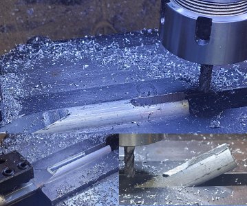
Drill and tap a 6-32 axle hole at the rear for an axle.
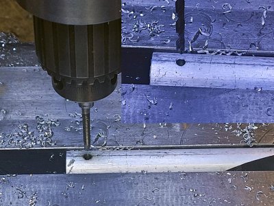
Jig on the bench. I didn't show it, but pressure is put on the wire with a piece of brass that bears on the wire.
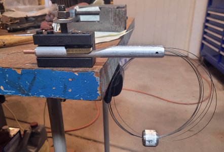
I used a piece of ¼” brass for a clamping plate to pin the wire to the fixture for tension. My original plan was to adjust tension using the existing QCTP tool holder set screw, but that would mean fiddling with an Allen wrench. So, chucked up some ¾” 303 stainless and made a clamp knob.
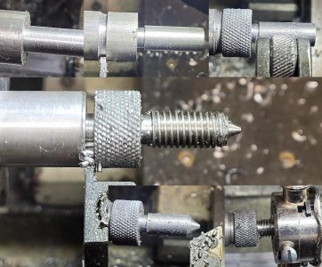
Adjusting screw from 303 stainless. This let me adjust the clamp pressure on the wire without fiddling with an Allen wrench in the QCTP holder. Happened to be an M10x1.5 thread. I didn't show it, but drilled a pocket in the brass plate to catch the tip of the clamping screw.
Next was making the mandrel which the wire would be wrapped around. The spring is wound around a mandrel under tension. When the tension is relieved, it springs back (pun intended) and the OD grows. Machinery’s Handbook has a table for the “fudge factor” as the mandrel is undersized relative to the final spring’s OD. In my case, the original spring was ~0.20” coil diameter with 0.020” wire diameter. The OD’s in my Machinery’s Handbook went from 3/16” (0.1875”) to 7/32” (0.21875”) so I'm about halfway between. A 3/16” OD spring from 0.020” wire takes a mandrel 0.123” diameter; 7/32” OD takes 0.144” diameter. I targeted 0.135” to get a spring OD of around 0.200”.
I started with a length of 3/16” CRS and drill a #58 hole for the starting point of the spring. Chucked up the 3/16” rod, center drilled and turned between centers to 0.135” diameter.
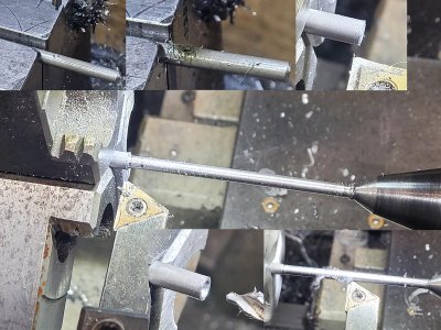
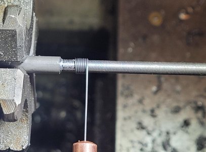
Winding went pretty quickly. I started with the extension spring with tight coils. I fed a ½” of music wire through the mandrel hole and bent it over as a stop. I started with the tension knob too tight; as I rotated the chuck the bent-over wire was pulling out of the mandrel. Backed off the pressure and rolled away. I manually rotated the chuck and moved the carriage to wind this one. I didn’t show any of the operations, but made a weight of such for the coil of wire from a 1” aluminum round. I fed the wire through a center hole in the aluminum looping it around and back through the hole. My hope (it worked well) was to keep the wire in check and not splay out as loosely setting on my bench it “wanted” to be in a 1’ circle.
Ready to go!
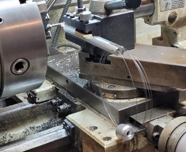
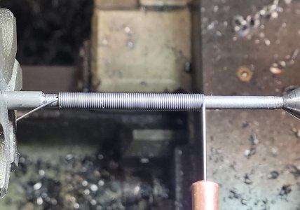
Next were the compression springs. These have a coil spacing of ~0.1”. I set the Grizzly lathe to 10 tpi and wound a spring. I slipped it over the 6-32 screw that’s used to adjust the Erector set “NV” whistle and noticed that the spring was snagging on the screw. Yup, I’d wound it in the wrong direction. When a spring goes over a RH screw, the spring should be wound like a LH screw so its coils can slip over the threads of the screw. A RH spring on a RH screw will catch the threads as the spring compresses. That's why I usually make a prototype!
Wound the compression spring on the bottom side of the mandrel to make a LH-wound spring (or whatever the proper term is).
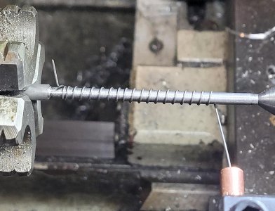
Before trimming to length.
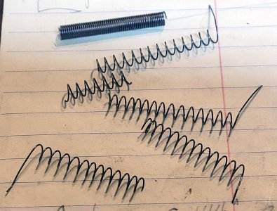
So, was it worth it making my own springs instead of buying them? I paid $8 including shipping for a 10’ length of 0.020” music wire. I found a source off eBay (from China) who has 10 springs 1” long that would have worked for $8. Of course, I’d make my own again! It’s shop time and I learned something! Plus, I’ll now look at buying bulk coils as I found some Precision Brand 0.020” stock on eBay at $20 including shipping for about 1000’.
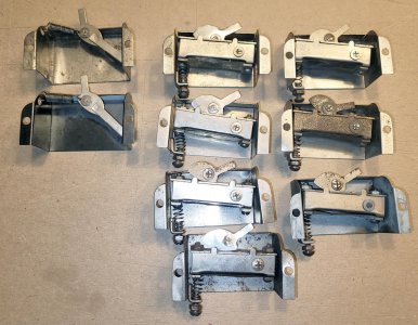
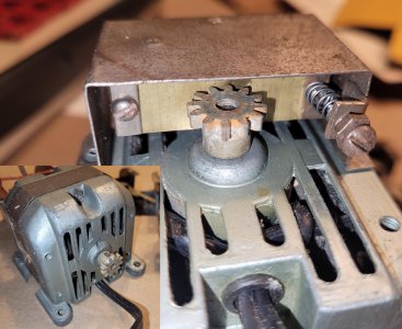
Erector part number "NV - whistle". These were sold in 1940 - 1946. The 1946 version (much simplified design) is to the left. The NV mounted to the back of the motor, pulling on the cam lever pushed a brass strip into a pinion gear on the back of the motor. They called it a whistle but it sounds more like a bearing screaming for oil.
Thanks for looking!
Bruce
I made the main body out of a 5/8” aluminum rod. The tip is from my Hobart MIG-welder. I happened to grab a 0.030” hole tip as my springs would be made from 0.020” music wire. Naturally, if I wind some larger springs, the tip will need to be drilled out.
My plan was to hold the jig in a QCTP tool holder. The front two set screws would clamp the jig in place, one of the back ones would be used to put a drag on the music wire. The wire needs to be under tension as it wraps on a mandrel, otherwise the coil size will not be consistent (too loosely wrapped around the mandrel).
Started by making a pass on the bottom side of the aluminum with an end mill. This would give a flat surface for mounting in the QCTP tool holder. Then flipped it and hogged out an area for the tension screw.
The 5/16" deep pocket was milled in the 5/8" rod with a 1/2" end mill. I had some 1/8" aluminum plates on either side of the round to spare my vise jaws.

Then over to the lathe to drill/tap the ¼”-28 threaded hole for the MIG welder tip. I ran the tap drill just through the solid rod and into the hogged-out area for the tension screw by 1/8” (though not super critical). I didn’t want to go real deep with the tap drill as the flat surface in the hogged-out area is where the music wire will be clamped to. If I went too deep with the drill, the clamping surface would be trough larger than the wire; no clamping force at that point.
Face, chamfer, center drill, tap drill and thread a 1/4"-28 hole.

Then back to the mill to add a tapered area behind the hogged-out area for wire feed clearance. Then ran a drill mill down the center of the clamping area about 0.005" deep to give the wire a small trough to run in. I used a ¼” roughing end mill to cut a slot at the very rear of the fixture for securing the music wire spool. Also milled a shallow trough in the top of the fixture from the spool to the tapered area to give the wire a place to run. Flipped the fixture to hog out a taper on the bottom of the wire spool area to give some clearance to the lead-top edge of the spool. Then drilled/tapped a 6-32 hole at the end for an axle for the music wire spool.
The round was oriented by setting the flat milled on the bottom on a square (though this wasn't super critical)

Milled a pocket at the back for the spool of wire. Also milled a shallow trough on top. Flipped and hogged out an area in the bottom to accommodate the forward/upper loop of the wire spool.

Drill and tap a 6-32 axle hole at the rear for an axle.

Jig on the bench. I didn't show it, but pressure is put on the wire with a piece of brass that bears on the wire.

I used a piece of ¼” brass for a clamping plate to pin the wire to the fixture for tension. My original plan was to adjust tension using the existing QCTP tool holder set screw, but that would mean fiddling with an Allen wrench. So, chucked up some ¾” 303 stainless and made a clamp knob.
Adjusting screw from 303 stainless. This let me adjust the clamp pressure on the wire without fiddling with an Allen wrench in the QCTP holder. Happened to be an M10x1.5 thread. I didn't show it, but drilled a pocket in the brass plate to catch the tip of the clamping screw.

Next was making the mandrel which the wire would be wrapped around. The spring is wound around a mandrel under tension. When the tension is relieved, it springs back (pun intended) and the OD grows. Machinery’s Handbook has a table for the “fudge factor” as the mandrel is undersized relative to the final spring’s OD. In my case, the original spring was ~0.20” coil diameter with 0.020” wire diameter. The OD’s in my Machinery’s Handbook went from 3/16” (0.1875”) to 7/32” (0.21875”) so I'm about halfway between. A 3/16” OD spring from 0.020” wire takes a mandrel 0.123” diameter; 7/32” OD takes 0.144” diameter. I targeted 0.135” to get a spring OD of around 0.200”.
I started with a length of 3/16” CRS and drill a #58 hole for the starting point of the spring. Chucked up the 3/16” rod, center drilled and turned between centers to 0.135” diameter.

Winding went pretty quickly. I started with the extension spring with tight coils. I fed a ½” of music wire through the mandrel hole and bent it over as a stop. I started with the tension knob too tight; as I rotated the chuck the bent-over wire was pulling out of the mandrel. Backed off the pressure and rolled away. I manually rotated the chuck and moved the carriage to wind this one. I didn’t show any of the operations, but made a weight of such for the coil of wire from a 1” aluminum round. I fed the wire through a center hole in the aluminum looping it around and back through the hole. My hope (it worked well) was to keep the wire in check and not splay out as loosely setting on my bench it “wanted” to be in a 1’ circle.
Ready to go!


Next were the compression springs. These have a coil spacing of ~0.1”. I set the Grizzly lathe to 10 tpi and wound a spring. I slipped it over the 6-32 screw that’s used to adjust the Erector set “NV” whistle and noticed that the spring was snagging on the screw. Yup, I’d wound it in the wrong direction. When a spring goes over a RH screw, the spring should be wound like a LH screw so its coils can slip over the threads of the screw. A RH spring on a RH screw will catch the threads as the spring compresses. That's why I usually make a prototype!
Wound the compression spring on the bottom side of the mandrel to make a LH-wound spring (or whatever the proper term is).

Before trimming to length.

So, was it worth it making my own springs instead of buying them? I paid $8 including shipping for a 10’ length of 0.020” music wire. I found a source off eBay (from China) who has 10 springs 1” long that would have worked for $8. Of course, I’d make my own again! It’s shop time and I learned something! Plus, I’ll now look at buying bulk coils as I found some Precision Brand 0.020” stock on eBay at $20 including shipping for about 1000’.
Erector part number "NV - whistle". These were sold in 1940 - 1946. The 1946 version (much simplified design) is to the left. The NV mounted to the back of the motor, pulling on the cam lever pushed a brass strip into a pinion gear on the back of the motor. They called it a whistle but it sounds more like a bearing screaming for oil.


Thanks for looking!
Bruce

