Small drill sharpening jig from junk.

Rob Thule

Registered
Registered
Joined
Feb 19, 2022
Messages
24
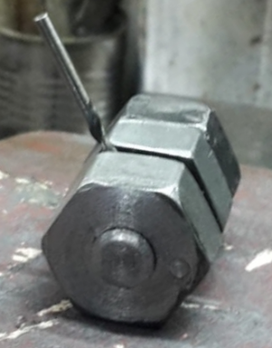
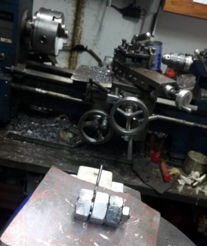
I hate using small drills, they break or even when new may have improper geometry. I came across a number of jigs to sharpen them, namely Lautard, Hall and Smeed’s. Since I was a bit sceptical I didn’t want to waste stock so I decided to make it from a few nuts and a piece of threaded rod.

Using the nuts allowed me to centre the groove that holds the drill quite easily and accurately. A side of the nut is aligned with the mill vise using a square, whilst an edge finder is used to find the nut’s centre.

You need a good glass to see what you are doing. I sharpened the drills on sandpaper and a diamond lapping plate. Had to fiddle a bit to get the drill geometry right but to my delight it worked. I soon dove into my hardened pin repository to fish out all the broken/dull drills I could salvage.
 

Attachments

  • Untitled s.png
    Untitled s.png
    266.2 KB · Views: 82
Hi Rob,

Maybe I am dense, but I don't get it.....

Is there hole drilled thru the bolt shank such that the drill tip sticks thru?
Do you then use the nut face running against the abrasive to maintain the angle?
How do you set the rotation of the drill bit?

I came across a number of jigs to sharpen them, namely Lautard, Hall and Smeed’s. Since I was a bit sceptical I didn’t want to waste stock so I decided to make it from a few nuts and a piece of threaded rod.

Is this based off one of those designs?
If so, which? so I can look it up and maybe understand what you're doing here.

Thanks,
Brian
 
Hi Rob,

Maybe I am dense, but I don't get it.....

Is there hole drilled thru the bolt shank such that the drill tip sticks thru?
Do you then use the nut face running against the abrasive to maintain the angle?
How do you set the rotation of the drill bit?


Is this based off one of those designs?
If so, which? so I can look it up and maybe understand what you're doing here.

Thanks,
Brian
Hi Brian,

yes the drill is inserted through a radial hole in the central pin. The nut face runs against the abrasive holding the drill at the desired angle. The drill is held in a groove and rotated by loosening a nut (not visible at the other end of jig) which screws on the central pin.

The pic I posted may be misleading. The nuts are solid to the threaded rod essentially turning them into a piece of hex rod. Smeed uses a steel block machined at 118 degree so I went for a hex design which has faces at 120 degree at each tip. Howard Hall and Lautard's are made from square bar.

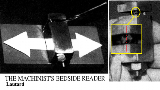
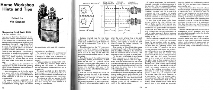
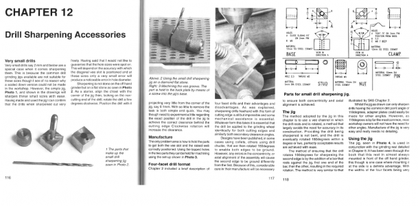
Attached are extracts from Lautard's (Machinist’s Bedside Reader 1), Smeed's (Workshop Practice Series 26_Home Workshop Hints and Tips) and Hall's (Workshop Practice Series 38_Tool and Cutter Sharpening) books which cover the design. The latter has features (not required) that may be difficult to machine accurately and any error would have consequences on the drill geometry.
 

Attachments

  • e4301ac2-2bae-4e30-ad12-b7c2227064a5.jpg
    e4301ac2-2bae-4e30-ad12-b7c2227064a5.jpg
    67.7 KB · Views: 42
  • lautard.png
    lautard.png
    242.1 KB · Views: 40
  • smeed.png
    smeed.png
    553.4 KB · Views: 45
  • Hall.png
    Hall.png
    414.6 KB · Views: 48
Last edited:
Hi Brian,

yes the drill is inserted through a radial hole in the central pin. The nut face runs against the abrasive holding the drill at the desired angle. The drill is held in a groove and rotated by loosening a nut (not visible at the other end of jig) which screws on the central pin.

The pic I posted may be misleading. The nuts are solid to the threaded rod essentially turning them into a piece of hex rod. Smeed uses a steel block machined at 118 degree so I went for a hex design which has faces at 120 degree at each tip. Howard Hall and Lautard's are made from square bar.

Attached are extracts from Lautard's (Machinist’s Bedside Reader 1), Smeed's (Workshop Practice Series 26_Home Workshop Hints and Tips) and Hall's (Workshop Practice Series 38_Tool and Cutter Sharpening) books which cover the design. The latter has features (not required) that may be difficult to machine accurately and any error would have consequences on the drill geometry.
I'm a little confused about the M6 hole in the top clamp of the third article design. It doesn't seem to have anything threaded into it. Could this just be a 6 mm recess for the knurled clamp nut? Metric drawings seem to confuse me. It is easy to get M6 and 6 mm mixed up. Unfortunate.
 
These kind of books need to be taken with a pinch of salt and examined carefully before committing to metal.

I am comparing the photo with the drawings to make sense of it.

I guess you are referring to feature C M6 hole. That is where the stud is threaded. However, the shaft is 5mm and the knob does not go there. I would guess that an M6 screw can be used to lock the shaft in place. Remember that the stud is cross drilled and said hole must be in line with the groove, plus it must resist turning forces applied to the knob. I simply tacked the stud in place.

Also feature B of the Base should not be threaded M5 but slip fit to allow the stud through.

My 2 cents.
 
Last edited:
Back
Top