Bandsaw vice modification.
The standard bandsaw vice works well for cutting long stock. For short stock it cannot clamp the workpiece. To solve this my first solution was to add an M8 jack screw to the movable vice jaw, as many others have done. This worked well but it was very slow to reset the vice for a new thickness of stock. Even with the jack screw it is still impossible to hold very short pieces. Angular adjustment of the standard vice is a real pain because in order to lock the fixed jaw after adjusting the angle it is necessary to grovel under the vice table to put a spanner on the lock nut. The angular scale on the side of the saw used to set the angle was a joke. It was very inaccurate and being only made of adhesive metal foil it started to peel off after a short space of time.
Inevitably, one day I had to cut a piece that was too wide to fit in the vice. This day came when I was making my tee slot faceplate.
In order to overcome these problems I have made a number of changes to the vice. these are:
1. On the moving jaw the slot in the jaw that allows the jaw to be positioned laterally has been eliminated.
2. Doing this means that a plate can be bolted to the vice jaw to extend it right over to the saw blade. Nothing is lost in this process since the ability to move the vice jaw is more than compensated by the extra length of the jaw.
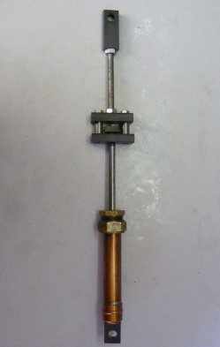
3. A jack rod has been added. This is not screwed but slides in a clamp block. It can be released with 1/2 turn of the clamping screw. This is much quicker and easier than a jack screw.
4. Nuts and screws on the moving jaw that have to be tightened or untightened often have been replaced by screws with tommy bars.
5. On the fixed jaw I have moved the pivot point about 15 mm closer to the bandsaw arm hinge. This gains extra working space enabling wider work to be cut.
6. Moving the pivot point means that the circular slot is no longer a radius to the pivot point. To compensate for this the fixed jaw has been slotted so that the lock nut can follow the curved slot.
7. The lock nut for the angular adjustment of the fixed arm has been replaced by a tee nut that runs in the curved slot of the vice table. This enable the vice to be locked from above rather than having to grovel under the vice table.
8. A new, more accurate, angular scale was engraved in a strip of aluminium that is screwed to the side of the bandsaw
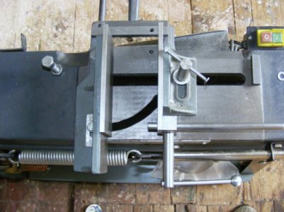
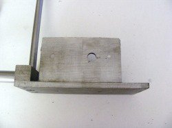
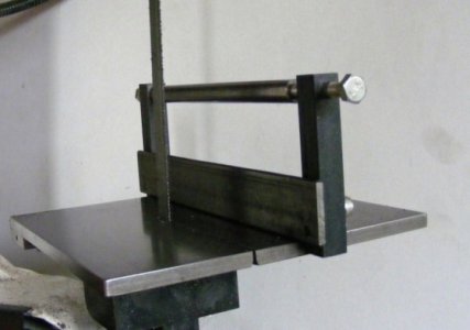
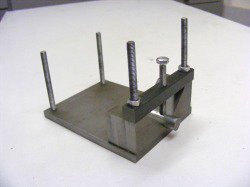
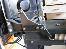
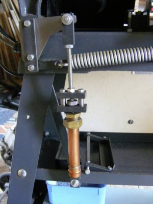
This shows the base of the moving jaw. A piece of 5 mm plate has been screw to the base with a single hole in it. This effectively eliminates the slot in the base of the moving jaw. On the vertical part of the jaw a piece of 6 x 75 mm plate has been screwed on so that extends right up to the saw blade. On the left hand side is the block in which the jack bar slides. The 10 mm diameter jack bar can be seen disappearing off the top of the photo and the locking nut off to the left hand side.
--------------------------------------------------------------------------------
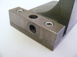
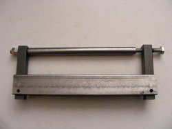
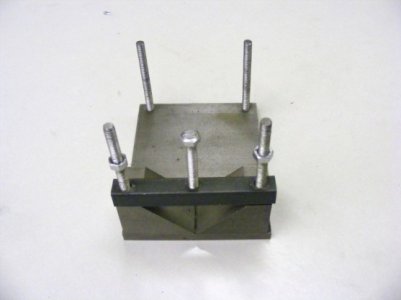
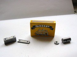
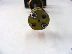
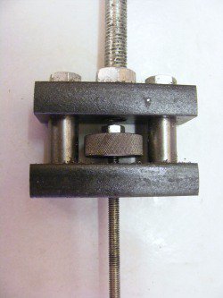
This photo shows the clamp block. It was made from a piece of 18 mm square bar and bolted to the plate by two 6 mm socket head screws.The vertical hole is for the jack bar and the horizontal hole is for the clamp pin.
--------------------------------------------------------------------------------
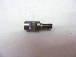
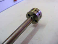
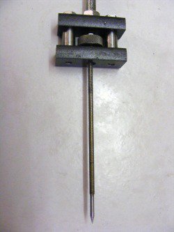
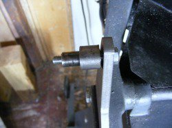
Here is the clamp pin. It is 10 mm diameter and the end is threaded M6. When the pin was originally made it had an additional thread extending from the left hand side. The two threads were used to lock the pin in the clamp pin hole before the 10 mm hole was drilled for the jack bar. This ensures that the crescent cut out aligns perfectly with the jack bar. The left hand threaded section was then turned off.
--------------------------------------------------------------------------------
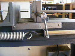
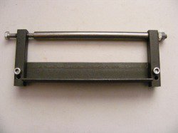
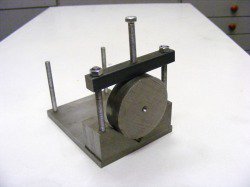
The header photo shows the nut for the clamp pin. This is a piece of 19 mm round bar which was drilled and tapped M6 that screws on the end of clamp pin. The other end is cross drilled with a 6 mm hole for a tommy bar. The tommy bar was made from a 6mm x 150 mm round wire nail. The head end of the nail was cleaned up on the lathe and the other end threaded for the ball.
The screw for clamping the vice jaw to the vice table is also a piece of 19 mm round bar. This has an M8 theaded male end that screws into the nut on the vice feedscrew. It is tall enough to clear the top of the vice jaw to allow easy use of the tommy bar. Again the tommy bar was made from a round wire nail.
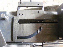
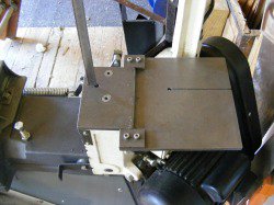
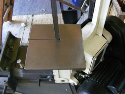
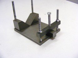
This photo shows the top of the vice table with the fixed jaw removed. Note the two closely spaced holes on the left hand side of the photo. These are the pivot holes for the fixed jaw. The one on the right is the original hole and that on the left is a new hole approximately 15 mm away. The holes are threaded M8.
Also note in this photo the two holes on the right hand side, either side of the blade slot. These are tapped 8 mm and can be used to mount faceplate clamps to hold objects for cutting.
--------------------------------------------------------------------------------
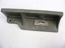
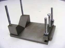
The new hole is not at the centre of the curved slot radius. The hole for the locking bolt has been slotted as shown in this picture so that the locking bolt can track the curve slot when the fixed jaw is moved. The casting was very rough at this point and it has been cleaned up roughly with a file and a small plate added for the clamp bolt to act on.
--------------------------------------------------------------------------------
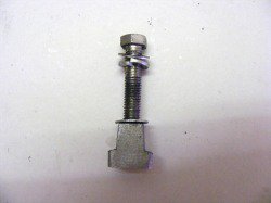
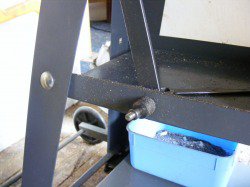
This is the clamp bolt with the tee nut that runs in the curved slot. The nut was produced by sawing and filing as no great accuracy is required.
--------------------------------------------------------------------------------
The photo shows the new aluminium engraved scale attached to the side of the bandsaw.
--------------------------------------------------------------------------------
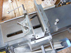
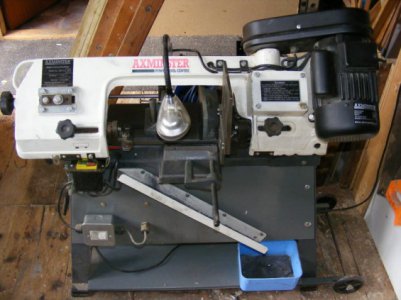
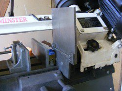
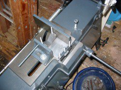
Here the band saw has been set up for cutting a short piece of steel. Notice the 6 mm plate on the fixed jaw. This plate is not fixed in any way to the jaw. It simply allows the fixed jaw to be extended out almost to the blade. To set this cut up the piece was first clamped somewhere near the centre of the jaws just over the vice feed screw. The jack bar was then loosened and pulled out until it hit the fixed jaw and then locked into position. The vice was loosened and the piece moved to the cutting position and the vice re-clamped
--------------------------------------------------------------------------------
