- Joined
- Sep 7, 2019
- Messages
- 674
Hey all! I've had a No. 700 for a long time and just finally want to get it bolted to my machine. The problem is I'm missing a few parts. I did a search and found some nice dimensioned drawings in the download section.
I need the clamp, draw bar and the pins. In the PDF at the bottom of the post I've circled the parts I need to make.
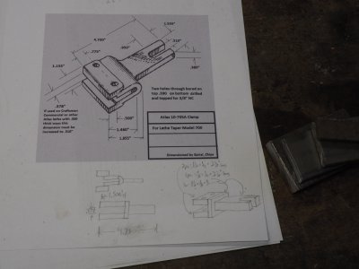
The most complex part is the clamp. Below is the drawing from the download section and my pencil interpretations are at the bottom of the page. I'm making a composite part of welded pieces.
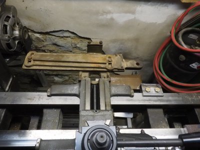
So far I have this.
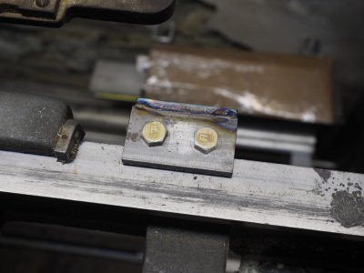
It goes on the ways snugly and it clamps very well.
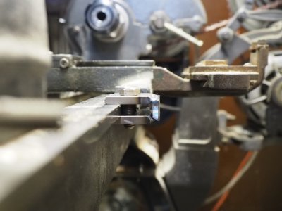
Now what I'm unsure about is the fitment of the taper attachment body to the clamp. I plan to make the slot in another piece of plate and weld it to the clamp, like so...
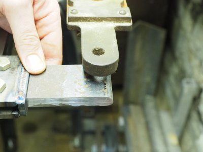
If I hold the rear plate in the center vertically of the clamp, I get about a 7/16" gap between the taper attachment body and the clamp. As far as I can tell this is normal, I think. I don't see a dimension for this on the drawing. If I hold the rear plate flush with the top weld I get a 3/8" gap to the taper attachment.
Below are a few more shots for clarity.
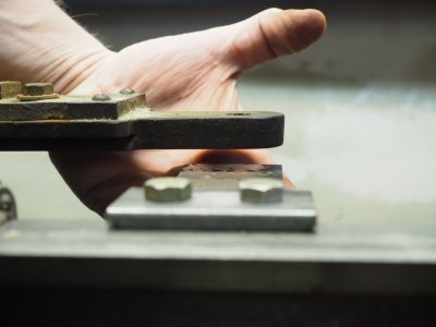
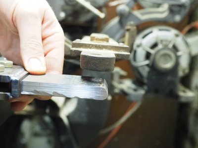
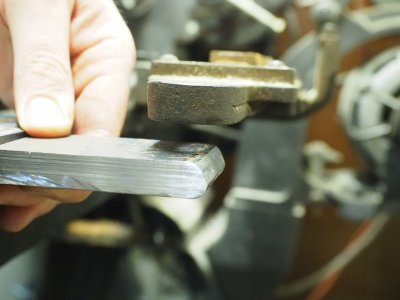
It looks like the rear plate could be made a little longer as well. But mainly I'm concerned with the gap between the clamp and the attachment. Will the gap there cause any kind of binding or play issues?
Also is the slot strictly necessary? Could I not simply drill a hole to connect these two parts? I'm assuming the fact that the clamp was slotted was so that the taper attachment could be made universal, and a slot would account for any small variations in manufacture of these machines and models.
Any insights would be greatly appreciated!
I need the clamp, draw bar and the pins. In the PDF at the bottom of the post I've circled the parts I need to make.
The most complex part is the clamp. Below is the drawing from the download section and my pencil interpretations are at the bottom of the page. I'm making a composite part of welded pieces.

So far I have this.

It goes on the ways snugly and it clamps very well.

Now what I'm unsure about is the fitment of the taper attachment body to the clamp. I plan to make the slot in another piece of plate and weld it to the clamp, like so...

If I hold the rear plate in the center vertically of the clamp, I get about a 7/16" gap between the taper attachment body and the clamp. As far as I can tell this is normal, I think. I don't see a dimension for this on the drawing. If I hold the rear plate flush with the top weld I get a 3/8" gap to the taper attachment.
Below are a few more shots for clarity.


It looks like the rear plate could be made a little longer as well. But mainly I'm concerned with the gap between the clamp and the attachment. Will the gap there cause any kind of binding or play issues?
Also is the slot strictly necessary? Could I not simply drill a hole to connect these two parts? I'm assuming the fact that the clamp was slotted was so that the taper attachment could be made universal, and a slot would account for any small variations in manufacture of these machines and models.
Any insights would be greatly appreciated!


