Rotary Table Puzzle

MontanaAardvark

Registered
Registered
Joined
Jan 3, 2015
Messages
400
I've been working with my rotary table for CNC G0704 mill system and can't get past an issue. I can't seem to get the table's center of rotation under my spindle.

The table is a 6" RDX table from Wholesale Tool, which seems to be fairly popular.

When I first stumbled on the issue, I was putting a piece of stock with layout lines scratched in Dykem under a pointy center finder. I set up the long dimension of the part to parallel my X axis, set as 90 degrees on the table, and then I would line up the point over one line, rotate the table 90 degrees (to 180) and line up the point over the other line. I went back and forth between 90 and 180 until the center where the lines crossed was under the center of my spindle. At one point, I decided to rotate the table completely. As I went past 270, I could see the point was no longer over the place where the lines cross. Same when I got to zero degrees (360). I marked the points with the center finder and measured between them. They were close to 0.032 apart. (Two holes marked in red to help you see them - when I laid the calipers over them, they were about that far apart, center to center. )
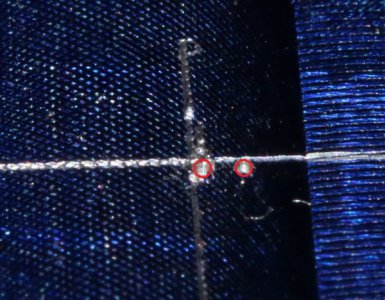
RotTableError.JPG
So I took off my work and switched to a DTI I have that measures with .0005" marks. I found the X coordinate for both edges of the hole and then repeated for Y. When I was done, I could set X or Y to the same numbers, + or -, and the DTI would indicate the same thing for the edges, within that .0005. So for both X and Y, 0.000 is the center of the MT2 taper in the table. Then I clamped a piece of thin aluminum to the table and using the finest engraving bit I have (which has a .010 tip) found that it cuts a circle that's about .035 in diameter (center of the path, not the very edges - those are about .050.

Again, it seems like the center of rotation of the table is not the physical center of the table. I didn't know that was possible.

Is this common?

How would I find the center of rotation, so I could put it under the center of the spindle? Is there anything else I can do?

The harder question is whether it matters to my project. I'm just starting out building one of the Philip Duclos flame eater engines. Since I'm not machining parts that have to match another exactly, I'm guessing no. This is cutting the outside profile of a support for the engine. The center of this will be cut with a boring head to match the diameter of the cylinder.


Bob
 
I've been working with my rotary table for CNC G0704 mill system and can't get past an issue. I can't seem to get the table's center of rotation under my spindle.

The table is a 6" RDX table from Wholesale Tool, which seems to be fairly popular.

When I first stumbled on the issue, I was putting a piece of stock with layout lines scratched in Dykem under a pointy center finder. I set up the long dimension of the part to parallel my X axis, set as 90 degrees on the table, and then I would line up the point over one line, rotate the table 90 degrees (to 180) and line up the point over the other line. I went back and forth between 90 and 180 until the center where the lines crossed was under the center of my spindle. At one point, I decided to rotate the table completely. As I went past 270, I could see the point was no longer over the place where the lines cross. Same when I got to zero degrees (360). I marked the points with the center finder and measured between them. They were close to 0.032 apart. (Two holes marked in red to help you see them - when I laid the calipers over them, they were about that far apart, center to center. )
View attachment 265843
So I took off my work and switched to a DTI I have that measures with .0005" marks. I found the X coordinate for both edges of the hole and then repeated for Y. When I was done, I could set X or Y to the same numbers, + or -, and the DTI would indicate the same thing for the edges, within that .0005. So for both X and Y, 0.000 is the center of the MT2 taper in the table. Then I clamped a piece of thin aluminum to the table and using the finest engraving bit I have (which has a .010 tip) found that it cuts a circle that's about .035 in diameter (center of the path, not the very edges - those are about .050.

Again, it seems like the center of rotation of the table is not the physical center of the table. I didn't know that was possible.

Is this common?

How would I find the center of rotation, so I could put it under the center of the spindle? Is there anything else I can do?

The harder question is whether it matters to my project. I'm just starting out building one of the Philip Duclos flame eater engines. Since I'm not machining parts that have to match another exactly, I'm guessing no. This is cutting the outside profile of a support for the engine. The center of this will be cut with a boring head to match the diameter of the cylinder.


Bob

Here is how I center my RT on the mill. I have mine set up to use the 4" 3 jaw chuck from my lathe. I mount a piece of stock in the chuck and position it so I will skim cut the stock. I then rotate the RT to cut the stock. The resulting cylinder is then perfectly centered on the axis of rotation.

Then I use my edge finder to find the surface the cylinder in +/- x and y and record the coordinates of each. With a DRO, it is a simple task. I line up visually on center in the y direction and then I zero the DRO on the- x surface and move to find the +x surface, without changing the y position. The center position is 1/2 the difference between the two positions or, in this case, 1/2 the +x position. I then set the x position to the center and repeat for the + and - y positions. This puts the mill spindle directly in line with the center of rotation of the RT.

Another approach would be to attach a test indicator to the mill spindle and rotate the spindle, adjusting x and y on the mill until the indicator reads the same at any place on the circumference of the cylinder. Here is an 3example of such a tool. https://www.amazon.com/Anytime-Tool...rd_wg=Iutln&psc=1&refRID=0YJFBGSC392MGEA5FS9K

This can be done without a DRO. It just requires a bit more ingenuity and work. In that case, I would suggest making witness marks with a Sharpie between the table and the saddle and the saddle and the the base and recording your dial readings. The witness marks will get you within one dial reading the dial will set you on position. Remember to take backlash into account.

Once you know the coordinates of the RT axis of rotation, you can locate work on the RT table in the same manner as you would on the mill table.
 
Since my spindle has #3MT, I use my live lathe center to get the RT centered, then bolt it down. Simple and accurate.
 
Here is how I center my RT on the mill. I have mine set up to use the 4" 3 jaw chuck from my lathe. I mount a piece of stock in the chuck and position it so I will skim cut the stock. I then rotate the RT to cut the stock. The resulting cylinder is then perfectly centered on the axis of rotation.

Then I use my edge finder to find the surface the cylinder in +/- x and y and record the coordinates of each. With a DRO, it is a simple task. I line up visually on center in the y direction and then I zero the DRO on the- x surface and move to find the +x surface, without changing the y position. The center position is 1/2 the difference between the two positions or, in this case, 1/2 the +x position. I then set the x position to the center and repeat for the + and - y positions. This puts the mill spindle directly in line with the center of rotation of the RT.

Another approach would be to attach a test indicator to the mill spindle and rotate the spindle, adjusting x and y on the mill until the indicator reads the same at any place on the circumference of the cylinder. Here is an 3example of such a tool. https://www.amazon.com/Anytime-Tool...rd_wg=Iutln&psc=1&refRID=0YJFBGSC392MGEA5FS9K

This can be done without a DRO. It just requires a bit more ingenuity and work. In that case, I would suggest making witness marks with a Sharpie between the table and the saddle and the saddle and the the base and recording your dial readings. The witness marks will get you within one dial reading the dial will set you on position. Remember to take backlash into account.

Once you know the coordinates of the RT axis of rotation, you can locate work on the RT table in the same manner as you would on the mill table.

Thanks, RJ,

My biggest issue with copying your method is not having a lathe chuck for the rotary table, just a clamping set. I can put my DTI in a collet and put the two in the mill's spindle. That's how I did the DTI tests I talked about.

I read what you're saying as the rotary table definitely has a center of rotation that's different than the physical center of the table, and that's what you're finding.

So since I can't make a cylinder, what if I use the cylinder that's the inside of RT (the MT2 taper)?

Let's say I put the DTI in the spindle and bring the spindle forward (actually table backwards) until it touches the wall of the MT2 taper, then rotate the table through at least one full turn. If it's wobbling, which is rotating about a point in the RT, but not its geometric center I should see it there, right? How would I adjust out the difference in zero of the axis? I think that's what I just did.

Figure that I have DROs because I run everything in Mach3 CNC and other than moving the machine by touching buttons or entering commands, it's just like hand wheels.
 
Since my spindle has #3MT, I use my live lathe center to get the RT centered, then bolt it down. Simple and accurate.

That's how I started out. Put my 2MT dead center in the RT and then centered the spindle over it by eye with a collet holding a center/edge finder. That's when I discovered that if I rotate the table 180 degrees from where I started, the two centers are no longer in line.
 
With my first rotary table and mill, I built an arbor to put in the spindle. The od matched the hole in the center of the table. Moved the table until things lined up. Not brutally accurate, but not bad. If you had a coax indicator, using the taper in the RT would be an excellent option. Test indicator would do same thing, just a bit more ackward.

The center of hole not on center of rotation thing is troubling. Set up a test indicator on one spot on the center taper hole, then rotate the table without moving the spindle, if the axis of rotation is different than the table center the indicator will move by twice the amount of difference, although that assumes any misalignment is only in one direction. In theory it should not move. If it doesn't move, then the problem is not the RT and need to get a better spindle to table center technique. If it does, maybe someone else has been inside one and can make a suggestion.
 
Magic, what leads you to believe that a rotary table will repeat within 5 tenths?
 
Thanks, RJ,

My biggest issue with copying your method is not having a lathe chuck for the rotary table, just a clamping set. I can put my DTI in a collet and put the two in the mill's spindle. That's how I did the DTI tests I talked about.

I read what you're saying as the rotary table definitely has a center of rotation that's different than the physical center of the table, and that's what you're finding.

So since I can't make a cylinder, what if I use the cylinder that's the inside of RT (the MT2 taper)?

Let's say I put the DTI in the spindle and bring the spindle forward (actually table backwards) until it touches the wall of the MT2 taper, then rotate the table through at least one full turn. If it's wobbling, which is rotating about a point in the RT, but not its geometric center I should see it there, right? How would I adjust out the difference in zero of the axis? I think that's what I just did.

Figure that I have DROs because I run everything in Mach3 CNC and other than moving the machine by touching buttons or entering commands, it's just like hand wheels.
While a chuck makes it easier, it isn't required. You can fix a piece of aluminum plate on the table and cut away to form a cylinder. If you make the cylinder large enough, you will be able to reuse it many times. You could also bore a hole and press fit a piece of stock into it. Or you could mount a vise on the table and put a piece of stock in the vise. Lots of ways to skin that cat.

You can use the central hole in the RT but I thought you were concerned that the table wasn't concentric with the RT axis of rotation. You should be able to find videos of aligning a mill spindle axis with a hole using a test indicator. It is exactly the same process. But if there is runout for your table, or more correctly, the central socket, the procedure won't work.

A question that comes to mind is if you have a CNC mill, why the need for an RT?
 
While a chuck makes it easier, it isn't required. You can fix a piece of aluminum plate on the table and cut away to form a cylinder. If you make the cylinder large enough, you will be able to reuse it many times. You could also bore a hole and press fit a piece of stock into it. Or you could mount a vise on the table and put a piece of stock in the vise. Lots of ways to skin that cat.
...
A question that comes to mind is if you have a CNC mill, why the need for an RT?

Easy one first:

A 4th axis has a lot of uses. In this case, though, I'm building an engine from an old book, so I don't have CAD models and GCode. I'm doing exactly what the author says, and treating my mill as a manual mill with DROs. This is my first piece of the engine and maybe it would be better to create the CAD models and do it as an 3 axis piece.

You can use the central hole in the RT but I thought you were concerned that the table wasn't concentric with the RT axis of rotation.

I was trying to figure out what could cause the zero to seem to be off. I used an engraving bit to cut a test piece. I spun the table 360 degrees and it should have just made a hole where the spindle was. Instead, it made a little donut, like it's not rotating around the point I find to be 0,0.
 
Easy one first:

A 4th axis has a lot of uses. In this case, though, I'm building an engine from an old book, so I don't have CAD models and GCode. I'm doing exactly what the author says, and treating my mill as a manual mill with DROs. This is my first piece of the engine and maybe it would be better to create the CAD models and do it as an 3 axis piece.


I was trying to figure out what could cause the zero to seem to be off. I used an engraving bit to cut a test piece. I spun the table 360 degrees and it should have just made a hole where the spindle was. Instead, it made a little donut, like it's not rotating around the point I find to be 0,0.
OK, that is the reason that I have an RT for the CNC as well. The reason for the donut is that the mill axis isn't centered on the RT axis. It can be off in both x and y. You just have to move x and/or y until the donut diameter goes to zero. With your method this would be a visual alignment and it can be done with a microscope but I prefer machining the cylinder and finding the surfaces for each axis. Firstly, it separates the location into two independent processes which is much easier than trying to figure out which axis is affecting the donut diameter. Secondly, it permits measurement with what is arguably our most accurate measuring tool.

Alignment of a vertical RT us similar but has some added difficulties. Depending upon which way the RT is set up , you have to make sure that the RT axis is parallel with a mill axis, x or y. If you trust the RT, you can assume that its table surface is perpendicular to the rotational axis and sweep the surface with your test indicator. If that alignment is questionable, you can still sweep but make a small circle where the table contacts the the test indicator stylus. Rotate the RT 180º and sweep across to intersect the circle. Position the RT so it reads the same on each side. Then you can check your table for perpendicularity by sweeping without the rotation. This check can be done both horizontally and vertically.

From there, I would perform a check similar to what I did for a horizontal mount. I would machine a cylinder using an end mill. I would then measure the diameter of the cylinder with a micrometer. The center will be half that diameter below the top of the cylinder.

My tool offset table uses a dial indicator as the master "tool". I use the TTS tooling system which has uses an off line height gage My dial indicator is set up with zero at the center of travel but any arbitrary reading could be used. I set my height gage to read zero with the dial indicator reading zero and all tool offsets are relative to that setting. The same can be done with a tool height setter mounted on the mill table. Or for that matter, the cigarette paper method.

To transfer the the offsets to the work coordinates, I would mount the dial indicator in the mill and zero it on the top surface of the machined cylinder, zero the z axis DRO, then move the mill table off to the side and drop the z by half the diameter of the cylinder and reset z to zero. In Mach 3, you have 254 sets of workspace coordinates; G54, G55,....G59 P254. I would assign one of them to the dial indicator. Using a tool height setter, I would zero the dial indicator. You will now have a reference on the mill to set your tools. Just remember to select the correct G5x for your tools. It sounds complicated but once you get into the rhythm of it, it is straightforward.

OK, now with z taken care of, you need to find x and y. I use a common edge finder to find the the RT center of rotation. I would find one side of the clinder, set it to zero, and then find the other side. One half that reading will be the location of the center of rotation. You needn't worry about accounting for the edge finder diameter as it is taken into account already. Also, since you are approaching the cylinder from opposite directions, backlash is canceled out. The position along the RT axis will depend on your work and can be set then as you would when working on the mill table.

Although aligning and locating the RT is involved, it only has to be done once when you mount the RT on the mill (providng you have properly recorded the positions). My RT on the mill/drill hasn't been removed in a decade. The 12" table is large enough that I can work from that surface. with some compromise in the z axis travel. (that and it weighs around 250 lbs.:) )
 
Back
Top