Rotary Table Fixtures

iosens

Registered
Registered
Joined
Feb 22, 2015
Messages
7
Hi

A few month sago I jumped into the cold water and bought a 6" rotary table.

I do love the functionality, I understand the dividing plates, but I have a real hard time to
fixate most working pieces to the table. There is not much room on a 6" table to set the step wedges for
the clamps especially if you need more than one...
I have a hard time to find the center of rotation of the work piece again once it was taken out of the
machine....

I know you can buy a chuck like for a lathe, but then you are loosing material and height again to clamp it.

Somehow this is all very unsatisfying and I cannot find any got literature except for dividing plate divisions on best practices on how to use a rotary table
correctly,

Thank you very much for any hints.
 
You can make a pallet to mount your work to. It can be a piece of aluminum plate, can even be larger than the table, can be round or square, and might have patterns of tapped holes and dowel holes. The idea is to make it mount firmly and repeatably to the RT, have a feature that keeps it centered, and allows you to use the fixture holes to mount your work pieces. The pallet can also be considered sacrificial, meaning you can run your cutter all the way through your work and slightly into the pallet. That allows easier and more rigid and flat setups. When the pallet gets too many scars in it you fly cut it down to a fresh or mostly fresh surface and keep on using it. So thick is better than thin. You can also drill and tap more holes as needed for new work pieces, while the RT stays pristine. This is just one idea. Be creative and try to make the fixture meet most of your current and projected future needs.

You will also want something to put in the center of your RT to center it the same way as the work.

As for re-centering your work, it is best if you can drill a center hole with a center drill when you are first mounting the work. Buy or make a ground 60 degree rod that is straight and hard and spins without runout, mount it in a collet, then bring the quill down or the table up and move the table around until the centering pin nicely enters the center drilled hole in the work. You are then re-centered. If you don't want to drill the center hole in the work for some reason, you may be able to use other features on the work to mount a shop made centering jig that can be reinstalled when needed to re-center the part.

Tom Lipton of Oxtools has some very good YouTube videos on this. There are other good videos on other channels as well. You can do a search on the home pages of Tom's channel for "pallet" and "centering" and you will find what you are looking for.
 
Last edited:
There are a number of methods. Here is one (copied from another web site which was copied from . . . . )

Guy Lautard describes something he calls "Osborne's Maneuver" in one of his Machinist Bedside Readers. He describes it a lot more clearly than I will, but in brief it's this:

Measure the O.D. of your table as exactly as you can.
Put an edge finder in the milling spindle.
Set one axis (say Y) so as you move the table along the X axis you're roughly on the table centerline. Move over until the edgefinder kicks out on the edge of the table.
Move the table along the Y axis until you're beyond the edge of the rotary table, then move the table along the X axis 1/2 the O.D. of the table.
Again move the the edge finder against the edge of the rotary table, this time in the Y direction, until it kicks out.
Repeat the move-half-the-table-OD move again, only this time move along the Y axis 1/2 the O.D. and bring the edge finder against the table along the X axis.
Repeat until you're as close as you want to be. The technique converges quite rapidly, especially if your first "guess" is relatively close.


Buy Lautard's book(s)! They're worth owning, anyway.
 
Thank you very much.

I have seen the "pallets" I guess I need to make one.

Thank you for the tip for the books by Guy Lautard, I had not seen them yet .
 
If you can approach the table from all four quadrants, here is the way that I center the table:
  1. Set the y position to the approximate center of the table and move to the left side of the table.
  2. Approach the table until the edge finder trips and note the position. I usually do this twice or three times to verify the the trip point is correct. Do not change the y position. Raise the edge finder and move across the table to clear the table to the right.
  3. Lower the edge finder to the same height as previously and move to the right side of the table. Repeat to verify and note the position.
  4. The center of the table is the average of the two positions, (L+ R)/2.
  5. Raise the edge finder to clear the table and move to that position. If you have a DRO, you can set the x axis to zero at that point. Move the edge finder to the rear to clear the table and lower it to the previous height.
  6. Move the edge finder to the table until it trips. Repeat to verify the position and record it. Raise the edge finder to clear the table and move move ac4roos until it clears the front edge. lower the edge finder to the previous height and move the edge finder to the rear until it trips. Verify the position and record.
  7. The center of the table is (F + B)/2. Lift the edge finder and move to that position. If you have a DRO, you can set the y axis to zero at that point.
This usually will be sufficient to center the table. If your original estimate of the y position was significantly off, you may want to repeat the x axis centering to verify.

This method corrects for any backlash in the x and y axes. With a DRO, you are set. If you are reading the dials, the position is at the halfway point of the lash you have in the axis. e.g., if your x axis has .004" of backlash you would have to add or subtract .002" depending upon which direction you are moving.

I have a 12" RT and cannot access all four quadrants so I clamp a piece of stock on the table and machine a cylinder with an end mill by rotating the table. I then use the above method to find the center.

At some point, it would be wise to verify that the edge of the table is concentric with axis of rotation of the RT. You can do this easily by rotating the table edge past a dial indicator. If the table is not true, it would be best to machine the cylinder and use that to center the table.
 
If you can find a 1" aluminum plate stock or CRS steel plate be sure to take a skim cut on both top and bottom to remove any dips or humps from the rolling process. If you know someone with a surface grinder they can do a better finish. Aluminum can be ground using spring steel holddowns. Sounds like a interesting project and hope to see finished photo(s).
 
Here is a good example of a pallet:
Rotary table starts at 4:25
 
Last edited:
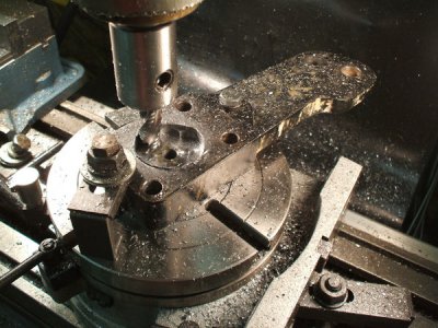
You have to be creative on some of the fixtures. I have an 8" table. Here Iam enlarging a king pin hole for a steering arm. I used a bolt and cone washer in an exsisting hole and then a hold down clamp on the opposite side.
DSCF1105_zpsnnusi8wu.jpg
 
John I just posted a couple pics of a plate I made for my 8" vertex. I kinda sorta copied Frank Fords approach. Mine is 12" X 1-1/4" thick , I would think 1" thick would be fine " and a lot easier to tap"
 
Hi

thank you again for all the replies.

I did get myself a 9" / 1 1/4 " thick aluminum plate. I should have gotten a 10" after all, but it just might have interfered with the drive wheel. But it is much better already. ( so far
I fly-cut the plate - (love fly cutters for the result, but hate the mess), and mounted it to the original table, will tab as needed.

Thanks again.
 
Back
Top