Background
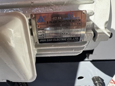
I have a Phase-A-Matic R-3 rotary phase converter which I have wired into my Precision Matthews PM-1440GT, which has a 2 horsepower 3-phase motor.
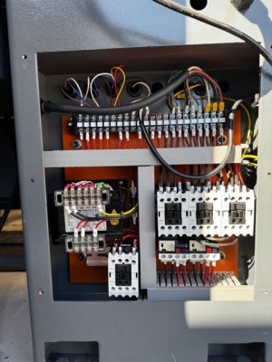
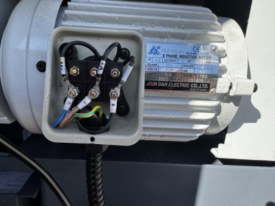
This phase converter has only three wires in its electrical box. The two hot legs from the wall are wired into the lathe and the rotary phase converter in parallel. The rotary phase converter produces a third "generated" leg.
I ensured the generated leg is on the contact labeled "T" (the other inputs, R and S, are used for low-voltage electronics). The ground connection is fine and I measured about 240 volts between R and S and 280 between T and the other legs while idle, which is expected. According to the specs this phase converter is large enough for the 2 hp motor in the lathe since it is 50% oversized.
Problem
The motor turns very slowly, maybe a tenth of the expected speed. I ran it at the slowest speed (50 RPM) to minimize load on the motor and got about 5 RPM. The speed is also inconsistent: it speeds up and slows down. After a short time (estimating 20 seconds) the motor breaker in the lathe trips.
What I tried
I tried switching the inputs around to every permutation and the one I started with is the only one that works at all.
Questions
1. Am I overlooking something? Are there steps to figure this out that I should take?
2. Do I need a voltage stabilizer? I hate to throw good money after bad. Based on a conversation with Phase-a-matic it doesn't sound like my lathe should need it, but who knows.
2. If I return this and get a solid state phase converter from Phase Perfect should I expect the same problems?
I have a Phase-A-Matic R-3 rotary phase converter which I have wired into my Precision Matthews PM-1440GT, which has a 2 horsepower 3-phase motor.
This phase converter has only three wires in its electrical box. The two hot legs from the wall are wired into the lathe and the rotary phase converter in parallel. The rotary phase converter produces a third "generated" leg.
I ensured the generated leg is on the contact labeled "T" (the other inputs, R and S, are used for low-voltage electronics). The ground connection is fine and I measured about 240 volts between R and S and 280 between T and the other legs while idle, which is expected. According to the specs this phase converter is large enough for the 2 hp motor in the lathe since it is 50% oversized.
Problem
The motor turns very slowly, maybe a tenth of the expected speed. I ran it at the slowest speed (50 RPM) to minimize load on the motor and got about 5 RPM. The speed is also inconsistent: it speeds up and slows down. After a short time (estimating 20 seconds) the motor breaker in the lathe trips.
What I tried
I tried switching the inputs around to every permutation and the one I started with is the only one that works at all.
Questions
1. Am I overlooking something? Are there steps to figure this out that I should take?
2. Do I need a voltage stabilizer? I hate to throw good money after bad. Based on a conversation with Phase-a-matic it doesn't sound like my lathe should need it, but who knows.
2. If I return this and get a solid state phase converter from Phase Perfect should I expect the same problems?