- Joined
- Oct 30, 2019
- Messages
- 225
Ever since I got the oil leaks fixed on my Colchester Chipmaster/Harrison 10AA and have started using it, I have daydreamed about how nice it would be to have the OEM FWD/REV/Stop buttons work as inputs to the VFD.
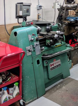
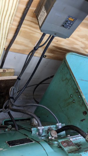
For the last few years up through when it finally got fixed early this year, it had the VFD mounted over the headstock on a bracket mounted off the back of the machine. This is wired directly to the 3hp motor, so start/stop/direction are all controlled using the integrated controls on the face of the VFD. The 3 pushbuttons on the machine itself and all of the electromechanical controls in the enclosure on the back are 100% unpowered/not in use (including the flood coolant system)
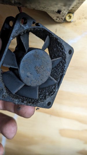
With the arrival of a 70s-era Bridgeport to my shop, which will share the same 30A/240v branch circuit as this lathe -- it was time to refactor the VFD setup on the lathe. The reason for these two things to go together is that the VFD was previously directly connected to the 30A branch circuit, so the VFD always had power (and a very loud fan), so I have been using the circuit breaker as a main power on/off for the VFD since fixing the lathe a few months ago.
Now that the Bridgeport is here and its VFD is on the same circuit, I needed a general solution for them to share but not always have power. For the bridgeport I repurposed an old 3-phase motor starter (just bypassed the overload protection since it didn't have the heater components and the VFD offers sufficient motor protection), so that its start/stop buttons latch the contactor and supply power to the VFD.
For the Chipmaster, I started down the same road originally:
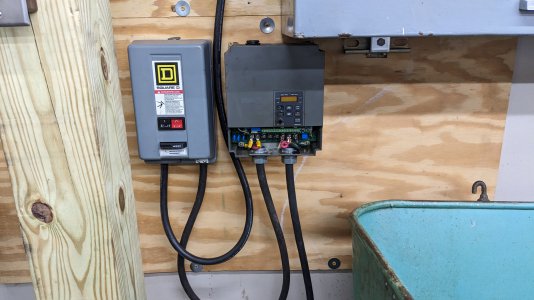
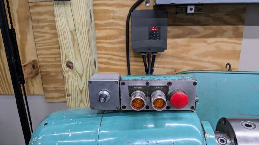
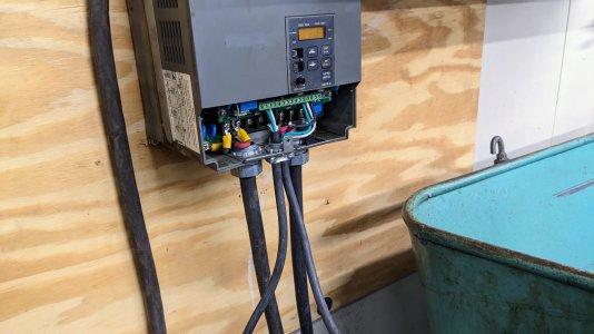
I mounted the VFD on the wall and put a repurposed motor starter next to it. I like using the motor starters for this purpose (as opposed to conventional disconnects) because if it's mounted on the wall, I can at some point extend the start/stop pushbuttons to somewhere closer to the operator if the wall becomes less convenient at some point. I originally did this with a couple of 3-phase drill press motors, where they came with motor starters but I needed a VFD to run them at home, and the pattern continued from there.
The setup pictured above worked fine, it met the need of letting me shut power off to the VFD locally instead of using the breaker. Of course, the VFD controls are now far less convenient when using the lathe, potentially unsafely so since they are positioned on the opposite side of the machine from the operator.
This brought me to seriously consider what would be involved in using the pushbuttons on the lathe as low voltage inputs to the VFD.
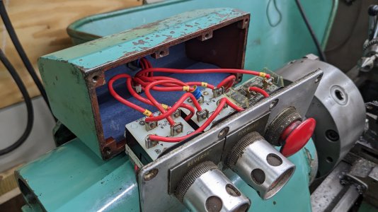
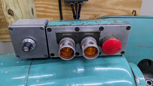
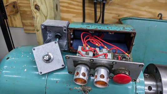
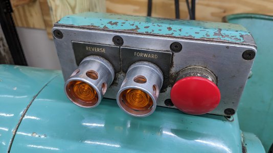
The FWD/REV buttons appeared to be momentary pushbuttons, with NO and NC contacts. Also they have terminals for a 120v backlight ... it would be really cool to get the backlight working!
Reading the VFD manual, it is similar to many -- it has numerous possible configurations for remote control buttons for various combinations of fwd/rev or start/stop and change-direction.... but all of these expect sustained contact/toggle behavior, not momentary contact.
This led to me thinking that I would need to design a basic circuit that used these buttons to latch one of two relays, with the stop button breaking power to both relays; and a 240>120v transformer to get the power for the backlights, since I don't have a neutral run to this machine on the 240v circuit it uses.
After about 10 minutes thinking on that, I realized I should take a look at what is inside the control enclosure on the back of the machine, since this sounds very similar to what would be done to drive two latching contactors for running a 3-phase motor in fwd or reverse.
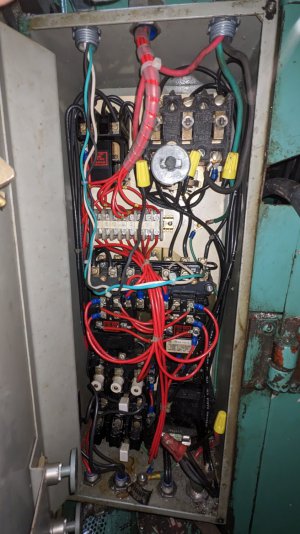
Sure enough, it has all the components you would expect to get the same latching behavior, but 3-pole contactors instead of relays since this would be switching the motor power directly. The picture above is after my minor changes:
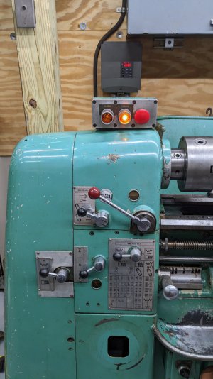
By using the original controls, the FWD/REV backlights automatically work -- they are wired to come on when the respective contactor is engaged. This is really satisfying for some reason!
After this success I looked more closely at what components make up this original small control cluster, and threw a few pieces in the ultrasonic cleaner to get off 50 years of grime. They cleaned up really nice.... now that I accidentally made a clean spot on the lathe, I may need to slowly start cleaning other pieces, we'll see. I don't do restorations, but piecemeal cleaning of functional bits may be in the cards.
Next steps:
Thanks for reading
For the last few years up through when it finally got fixed early this year, it had the VFD mounted over the headstock on a bracket mounted off the back of the machine. This is wired directly to the 3hp motor, so start/stop/direction are all controlled using the integrated controls on the face of the VFD. The 3 pushbuttons on the machine itself and all of the electromechanical controls in the enclosure on the back are 100% unpowered/not in use (including the flood coolant system)

With the arrival of a 70s-era Bridgeport to my shop, which will share the same 30A/240v branch circuit as this lathe -- it was time to refactor the VFD setup on the lathe. The reason for these two things to go together is that the VFD was previously directly connected to the 30A branch circuit, so the VFD always had power (and a very loud fan), so I have been using the circuit breaker as a main power on/off for the VFD since fixing the lathe a few months ago.
Now that the Bridgeport is here and its VFD is on the same circuit, I needed a general solution for them to share but not always have power. For the bridgeport I repurposed an old 3-phase motor starter (just bypassed the overload protection since it didn't have the heater components and the VFD offers sufficient motor protection), so that its start/stop buttons latch the contactor and supply power to the VFD.
For the Chipmaster, I started down the same road originally:

I mounted the VFD on the wall and put a repurposed motor starter next to it. I like using the motor starters for this purpose (as opposed to conventional disconnects) because if it's mounted on the wall, I can at some point extend the start/stop pushbuttons to somewhere closer to the operator if the wall becomes less convenient at some point. I originally did this with a couple of 3-phase drill press motors, where they came with motor starters but I needed a VFD to run them at home, and the pattern continued from there.
The setup pictured above worked fine, it met the need of letting me shut power off to the VFD locally instead of using the breaker. Of course, the VFD controls are now far less convenient when using the lathe, potentially unsafely so since they are positioned on the opposite side of the machine from the operator.
This brought me to seriously consider what would be involved in using the pushbuttons on the lathe as low voltage inputs to the VFD.

The FWD/REV buttons appeared to be momentary pushbuttons, with NO and NC contacts. Also they have terminals for a 120v backlight ... it would be really cool to get the backlight working!
Reading the VFD manual, it is similar to many -- it has numerous possible configurations for remote control buttons for various combinations of fwd/rev or start/stop and change-direction.... but all of these expect sustained contact/toggle behavior, not momentary contact.
This led to me thinking that I would need to design a basic circuit that used these buttons to latch one of two relays, with the stop button breaking power to both relays; and a 240>120v transformer to get the power for the backlights, since I don't have a neutral run to this machine on the 240v circuit it uses.
After about 10 minutes thinking on that, I realized I should take a look at what is inside the control enclosure on the back of the machine, since this sounds very similar to what would be done to drive two latching contactors for running a 3-phase motor in fwd or reverse.

Sure enough, it has all the components you would expect to get the same latching behavior, but 3-pole contactors instead of relays since this would be switching the motor power directly. The picture above is after my minor changes:
- I wired input power to enter the lower right corner of the enclosure, where there was already a knockout and strain relief
- This feeds L1/L2/L3 (line side) on the main power disconnect in the upper right. This is controlled by the lever on the cover when the enclosure is closed
- The load side of that mechanical disconnect, T1/T2/T3 were previously connected to a number of places:
- The fwd/rev contactors L1/L2/L3
- The flood coolant pump
- The 120v transformer in the lower right (fed from T1/L1 and T3/L3 only; so I made sure those were the poles where my 240v were connected)
- I disconnected the power from the disconnect to the fwd/rev contactors' input, since my goal was to have those contactors provide switching for the VFD low voltage now. This is the 3 yellow wire nuts shown just below the main disconnect in the upper right corner, they cap off the conductors going to the input of the contactors.
- I connected one of those contactor input conductors, L1 to the low voltage common line from the VFD, the black wire entering the top left corner of the enclosure - this is a new hole and strain relief I added to the enclosure
- I connected the new white and green wires from the upper left to the output T1 of the fwd/rev contactors. In FWD, the FWD contactor connects the green conductor to the black common conductor; and in REV, the REV contactor connects white instead of green.
- White and green in turn go to the FWD/REV inputs of the VFD

By using the original controls, the FWD/REV backlights automatically work -- they are wired to come on when the respective contactor is engaged. This is really satisfying for some reason!

After this success I looked more closely at what components make up this original small control cluster, and threw a few pieces in the ultrasonic cleaner to get off 50 years of grime. They cleaned up really nice.... now that I accidentally made a clean spot on the lathe, I may need to slowly start cleaning other pieces, we'll see. I don't do restorations, but piecemeal cleaning of functional bits may be in the cards.

Next steps:
- The one remaining control that is only on the front panel of the VFD is the speed/frequency adjustment via the front panel potentiometer
- This can be controlled remotely in a number of ways, one of which is via a 10k potentiometer
- I found a neat old precision potentiometer on ebay, it has a course and fine adjust. Overkill but seems a compatible vintage for the aesthetics of this machine (early-mid 70s)
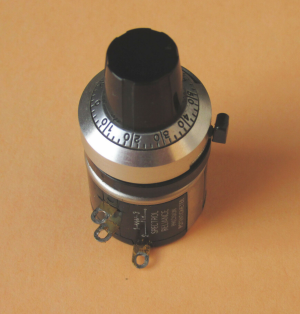
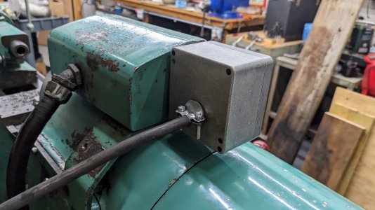
- I was originally thinking some compact pot that I could mount inside the existing pushbutton control enclosure, but there just isn't enough space inside and on the faces of it to do a clean job. Also, the flex conduit that goes from the control pod to the control enclosure is 100% full of the existing conductors, there is no way I could fit in another 3 wires required by the pot
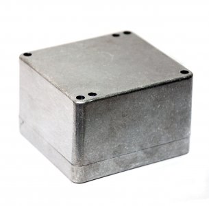
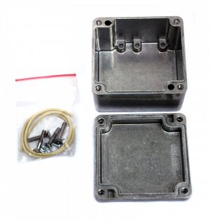
- So instead I am going to add a cast aluminum enclosure that is similar in height to the existing control pod casting. I'll either attach this with magnets or drill some holes to bolt this to the side of the existing pod. Then I'll run a 3-conductor wire from the back of the new enclosure to the VFD, for the potentiometer.
Thanks for reading
Last edited:

