resurrecting a clone - looking for some dimensions and advice

desbromilow

Registered
Registered
Joined
Sep 4, 2012
Messages
22
G'Day,
I haven't bragged too much yet about a Herless clone I dragged out of a skipbin. It's a variable speed head (2HP) and missing some parts, and other parts damaged.
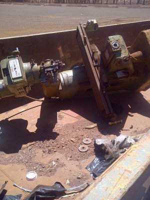
herless_bin.JPG

Whilst I'm working on repairing the broken parts, I hoped someone can help me out with some dimensions, and maybe some photos of some parts I'm missing.
The Mill has metric axis screws, but all missing parts have imperial threads.
I am missing every single knob off the head - from other photos they appear to be black balls around 1" in diameter - is that correct? (I know they are 1/4"-20 threads except the spindle brake which is 3/8"-16)

Is the spindle brake knob a different diameter?if so, what size?
How is the spindle brake operated? (it appears to be something I'd turn, but mine is not moving) Does the spindle need to be turning to engage the brake? any other tips as to moving the spindle brake? (or warnings regarding operating it without power?)

The Quill handles are all missing:
The lever - I know it's 3/8"-16 thread - but what shaft diameter? length? Ball diameter?
The handle (the rotating one at the front)
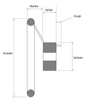
I know the bore diameter, but what is the depth of the hub? How deep s the handle (from back of hub, to front of rim) Rim diameter?
What is the length of the protruding pin?
The reversing knob... all I see is a small brass bush about 1/4" with a small threaded hole in it. The brass bush is nearly flush with the end of the shaft when "in", and protrudes around 3/16" to 1/4" when pulled out. What is the thread of the hole? (I suspect 12-32 or 10-32 but unsure since the taps aren't easily turning in)
What does the missing button/knob look like? - made of anything particlur? (plastic, brass, steel)
How is it retained (screw, or threaded shaft)?
How far should it come out when operated?
Is it spring loaded, or simply a sliding movement?

I've freed up the quill lock, and the micrometer depth stop. Found the Hi/Neutral/Lo back gear system can engage if I turn the spindle by hand

That's been all I've been able to figure out thus far - hopefully more functions will be operable once I get the motor running, but that will involve restoration of the damaged wiring, plus access to 3 phase outlet.

I'll be making a replacement knee handle soon, then working on repairing the snapped Y axis screw... most of the other repairs are fairly straight forward after those.

Many many thanks in advance for this information.
Des
Oz

herless_bin.JPG
 
You can get the knobs from the eBay seller zorotools for very reasonable prices. I just purchased all 8 of the 1" 1/4-20 knobs for my Bridgeport head there for $14 including shipping. They were $5-8 each elsewhere!
 
G'Day,
I haven't bragged too much yet about a Herless clone I dragged out of a skipbin. It's a variable speed head (2HP) and missing some parts, and other parts damaged.
View attachment 52351

Whilst I'm working on repairing the broken parts, I hoped someone can help me out with some dimensions, and maybe some photos of some parts I'm missing.
The Mill has metric axis screws, but all missing parts have imperial threads.
I am missing every single knob off the head - from other photos they appear to be black balls around 1" in diameter - is that correct? (I know they are 1/4"-20 threads except the spindle brake which is 3/8"-16)

Is the spindle brake knob a different diameter?if so, what size?
How is the spindle brake operated? (it appears to be something I'd turn, but mine is not moving) Does the spindle need to be turning to engage the brake? any other tips as to moving the spindle brake? (or warnings regarding operating it without power?)

The Quill handles are all missing:
The lever - I know it's 3/8"-16 thread - but what shaft diameter? length? Ball diameter?
The handle (the rotating one at the front)
I know the bore diameter, but what is the depth of the hub? How deep s the handle (from back of hub, to front of rim) Rim diameter?
What is the length of the protruding pin?
The reversing knob... all I see is a small brass bush about 1/4" with a small threaded hole in it. The brass bush is nearly flush with the end of the shaft when "in", and protrudes around 3/16" to 1/4" when pulled out. What is the thread of the hole? (I suspect 12-32 or 10-32 but unsure since the taps aren't easily turning in)
What does the missing button/knob look like? - made of anything particlur? (plastic, brass, steel)
How is it retained (screw, or threaded shaft)?
How far should it come out when operated?
Is it spring loaded, or simply a sliding movement?

I've freed up the quill lock, and the micrometer depth stop. Found the Hi/Neutral/Lo back gear system can engage if I turn the spindle by hand

That's been all I've been able to figure out thus far - hopefully more functions will be operable once I get the motor running, but that will involve restoration of the damaged wiring, plus access to 3 phase outlet.

I'll be making a replacement knee handle soon, then working on repairing the snapped Y axis screw... most of the other repairs are fairly straight forward after those.

Many many thanks in advance for this information.
Des
Oz
Des, I am sorry, I didn't answer your questions. I will answer as many as I can with my limited knowledge.
My quill lever is 3/8" thick, and about 12" long. I say about because it is broke where the threads begin for the knob.
The fine feed wheel on the front of the head is missing on mine too. So, I don't know the dimensions. But, it appears to have a pin that engages the hub like the quill feed lever does.
The feed reversing knob that is in the middle of that wheel, and goes in and out is knurled steel or brass (I have seen both) with a screw that holds it in. Mine is missing too. When I get back home, I will try to find out the thread size.
All of the other knobs are a black plastic with metal inserts for the threads.
I hope this helps you.
 
Thanks Mike!!!
I'll start on the quill lever based on what you've mentioned.

I may have hit a lucky run with the knobs - My Dad has a box of knobs which were from a closed down tractor repair shop - he says there's several round knobs in 3 sizes - one around 1", and then 2 sizes bigger
I'll start the restoration with those and adjust as required if they prove inadequate/uncomfortable

If I find any information from other sources on the fine feed handle, or the reversing button, I'll copy it here so you can build one too

Thanks, all for any help in this...


Des


Des, I am sorry, I didn't answer your questions. I will answer as many as I can with my limited knowledge.
My quill lever is 3/8" thick, and about 12" long. I say about because it is broke where the threads begin for the knob.
The fine feed wheel on the front of the head is missing on mine too. So, I don't know the dimensions. But, it appears to have a pin that engages the hub like the quill feed lever does.
The feed reversing knob that is in the middle of that wheel, and goes in and out is knurled steel or brass (I have seen both) with a screw that holds it in. Mine is missing too. When I get back home, I will try to find out the thread size.
All of the other knobs are a black plastic with metal inserts for the threads.
I hope this helps you.
 
Folks,
in order to help clarify some of the missing information I'm still chasing, I've done up these sketches.

This first one asks for some key dimensions from the Quill fine feed handle which is typically mounted on the front of the mill head. I've presumed the bore will be a slip fit on the protruding shaft, so have not requested that dimension.


quill_finefeed_dimreq.JPG

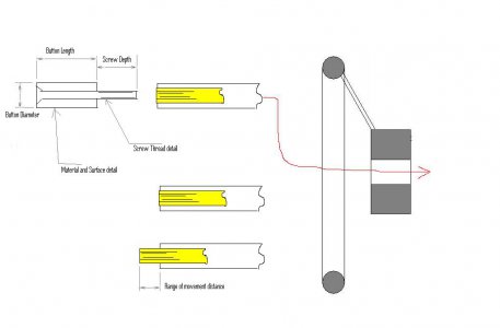
The second sketch is of the brass sleeve I found inside the shaft. According to the instruction manual, this must be linked to the reverse button mechanism.
My shaft has the sleeve protruding just a hair, but I can pull it forward by around 3/16" (5mm) - I found some fine screw threads inside the brass sleeve, but none of my taps slipped in easily (slight burr on sleeve opening)
On the build photos of RandyM's restoration, I can see the button is a cylindrical shape, retained by a countersunk screw, so I've sketched it that way... Mike says it could be made of brass or steel - so I've left the material as a question
Is it knurled?
How far does the button move (backwards or forwards) when operated? (the instructions imply a FWD, Neutral, and Reverse position - hard to imagine all of that in only 3/16" travel) - Does the button "click" in each of the three positions?


reverse_button_dimreq.JPG


Once I have these answers, I can build the missing parts.
I will still have questions regarding the engagement of the spindle brake, but one thing at a time.

thanks again in advance,
Des

quill_finefeed_dimreq.JPG reverse_button_dimreq.JPG
 
Last edited:
I don't have a bunch of numbers for you, but I do have info and ideas. Handwheels that need some finishing are available from grizzly and I'm sure others. The handwheel dimensions that you need are in the pieces of the mill you have. You need to do some measuring and fill in your blanks. There is a collar behind the handwheel that houses a spring and ball. That should give you a good idea of the hole pattern to line the pin up. Measure the depth of the pin hole in this collar to determine how far out of the handwheel the pin should protrude. And so on.
 
I know it's a clone, but there are bport rebuild books. They helped me out a LOT. Published by Ilion Industrial Services. I think you need the variable speed one. The piece you are wanting that has a small threaded hole in the end of a small shaft that is inside of a larger shaft is the clutch rod. it is long and thin and gets pinned through a slot in the larger shaft(worm shaft) It gets pinned into the feed reverse clutch that pulls back and forth to engage one of two gears thus selecting feed direction. In the middle-ish of the clutch rod there are three dips in the shaft, fwd neutral rev. The collar behind the handwheel has that spring and ball that slip into these semicircular grooves(dips). These give it a positive snap into position. It is possible that a Bridgeport part would work for you. H&W machine repair can get you the book and the part very reasonably. I would start with the book and tear the head apart. That shaft has to be pinned through the worm shaft for it to engage fwd or rev. I think I have all that right, But I know the book helps a lot when you don't know what you are looking at or what is missing. Coming from experience.
 
A tractor supply place would have a variety of small allen head cap screws. if you grab a screw that fits, thread it into the clutch rod and push and pull you should feel three positions. Push it all the way in and it should be about flush with the worm shaft end, and bump out twice when you pull it. You might need to turn some gears to get all the shifts. Good luck. Hope you come up with all your positions.
 
LEEQ,
Thanks for the advice, I hope to find out what the thread is, since it is around 4mm ID, which implies either #8 or #10 screws. The pitch seems around 32 tpi - but I do not want to spin in the wrong screw or tap and damage the internal threads.

Thanks to what you've said here, the detents should be able to be felt once I have a good grip on the rod, I will be back in front of the mill on the weekend, so will test the instructions then, plus any other advice I can obtain.

Thanks again,
Des


A tractor supply place would have a variety of small allen head cap screws. if you grab a screw that fits, thread it into the clutch rod and push and pull you should feel three positions. Push it all the way in and it should be about flush with the worm shaft end, and bump out twice when you pull it. You might need to turn some gears to get all the shifts. Good luck. Hope you come up with all your positions.
 
Thanks for the diagrams Des. Lee is correct, you really need to get the rebuild book. It will answer all of your "How does this work?" questions. I found the book to be priceless, It also shows all the little tricks to dissassemble the machine easily. Go to H&W's website, they have exploded diagrams on how this stuff goes together. I printed of the diagrams you posted and will try and get you the info you are requesting. Be patient as it may take me a couple of days.
 
Back
Top