- Joined
- Feb 1, 2015
- Messages
- 9,994
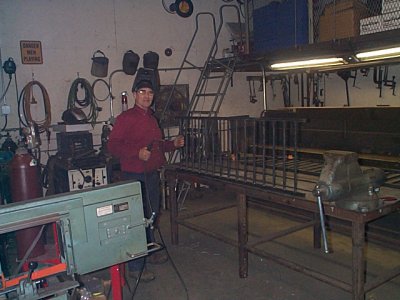
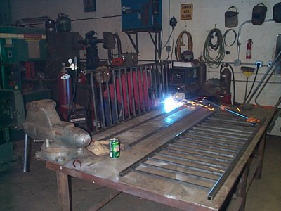
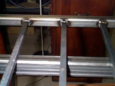
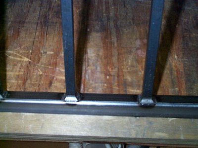
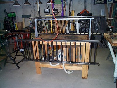
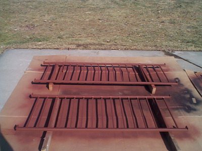
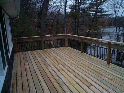
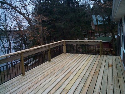
I have a large project consisting of making a deck railing. I am using 1/2" sq. HR for the spindles that has been stored in my barn for the past 30+ years and need to remove the surface rust. I have 80 of these to do, along with the top and bottom rails and have found the quickest way to remove the rust was with my B&D belt sander with a 60 grit belt.
Things were going smoothly until the sander slowed down drastically and ground to a halt. I Disassembled it and found that the bearing on the drive end had seized up and the outer race had chowdered the plastic housing to the extent that the armature was rubbing on the field core. The bearing was a 607 ZZ and I happened to have a spare although only with a single shield so I ordered two replacements (from JSB Great Bearings in Ann Arbor, MI; the two were slightly more than the cost for one and it is a bearing that I use). Meanwhile I had to repair the bearing housing. The plan was to use JB weld to build up the damaged housing. Rather than using the old bearing to create the bearing seat, I turned an exact replica from Delrin . Additionally, I turned two washers to sit on either side of the bearing to prevent the JB Weld from getting into places it wasn't supposed to.
The next problem was to restore the concentricity to the assembly. I measured the clearance between the armature and the field to be .019". A wrap of .010" aluminum shim stock and two wraps of .004" painter's masking tape brought me to .018". Additionally, the through hole on the housing was still intact so I made a shoulder to fit closely on the outboard washer.. These two steps ensured that I was maintaining respectable concentricity.
To prepare the housing, I cleaned it thoroughly and used a very fine tip on my soldering iron to poke eight small holes around the perimeter, the purpose to provide extra purchase for the epoxy bond. I stacked the washers and bearing surrogate on the armature and fitted the armature to the main housing. Then I mixed a small amount of JB Weld and coated the perimeter of the bearing housing, working it in until the JB was extruded through the previously made holes. Next, I assembled the two halves of the housing and fastened it, cleaned the epoxy that had pushed out along the armature shaft, and added the outboard washer and pulley/nut. When I mix epoxy, I always leave a small sample to test for curing before I disturb the repair. When the sample was hard enough, I disassembled the housings, pulling the drive side, complete with the armature. A simple twist of the armature after removing the nut was sufficient to free it from the housing. Next, I removed the bearing surrogate and inboard washer from the armature and the shoulder washer from the housing and installed my replacement bearing. All wen together nicely and the armature now spun freely so I installed the brush assemblies and reassembled the sander.
The sander works again like new and I am back in business. Unfortunately, my main objective was to return functionality as quickly as possible so I didn't take the time for a complete set of photos. Here is a photo of the surrogate and two washers along side of the OEM bearing. An autopsy of the dead bearing showed that the bearing spacer had failed, jamming the balls up and locking the bearing. There was very little lubricant left in the bearing which may have been the root cause of the failure. In spite of this, I couldn't see any sign of galling of either the races or the bearings. The sander had seen many years of hard use so failure wasn't too much a surprise.

Last edited:

