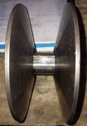
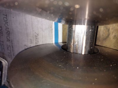
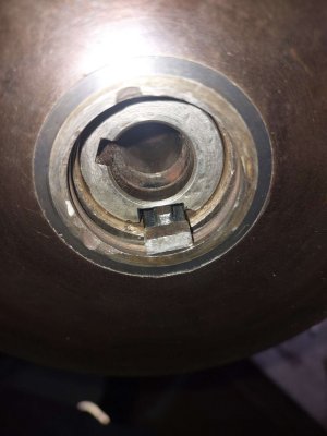
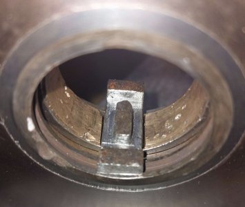
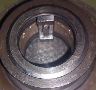
My first inclination is to install some type of self-lubricating bearing at the wear interface, but I have no idea if that is practical. This is a very common type of variable speed drive, used in everything from Bridgeports to go-karts. I would look into how this unit varies from other designs.
It did cross my mind too. Perhaps one could be machined from a Teflon rod.
I did search for information on other aplications of this drive, but it seems it is always drawn with no details whatsoever, but I found some bridgeport disassembly videos, likewise for a combine harvester with such drive. It appears those shown all just have a bushing press fit in the pulley that slides on the shaft. Leave it to Germans

to overcomplicated the design with ball bearings, multiple seals, very fancy micro-milled keys with ball bearing passages... Then their super complex design fails the same. Oh, well...
I also found a maker mark, so it seems the factory that made the machine didn't make it as it has remains of "Eberhard Zeng Ko" sticker. Perhaps someone heard of this maker?
There is also an alternative solution I didn't expect.
Specifically there are 4 wheels (2 sets). On the good side the moving wheel is spring loaded, the "stationary" just sits there at the back of the shaft.
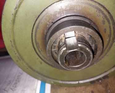
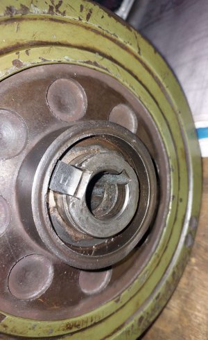
Now, the best part. After careful disassembly of the "good" side I believe all 4 wheels started as exactly the same. Even "stationary" wheels had the ball bearings inside and can in fact move along the shaft. Later someone modified/lost them on the bad side of the gearbox. This means that I essentially have a spare wheel on the good side. So I could simply use it on the other side if the shaft was in good condition. Sadly it isn't that great so I keep this option open for future.
Regarding grease migrating away. I discovered in the good side there are supposed to be seals too. I managed to get o-rings that should work as those seals.
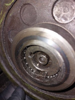
So I decided to make do with the currently, slightly undersized shaft, to set the stationary wheel with its key as a light press fit. I bought those 3mm ball bearings and I made the key in a shape that retains the grease and balls.
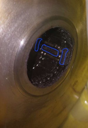
Balls are in a ring around the shaft on both sides of the wheel, and they are in the keyway. The "good" key is relieved on both sides enough so balls can be present along its mating surface with the shaft keway. So the key rides in its way on ball bearings.
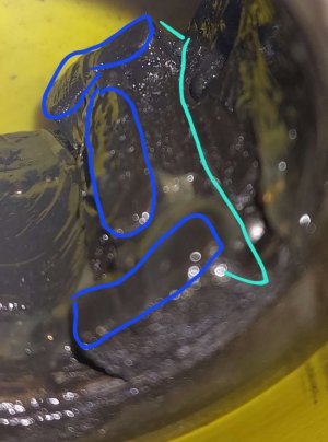
However, not everything is clear to me. The problem I now have is that I imagined the balls would roll and work as in THK linear bearings for example, but there is no way those balls can recirculate in this design! There is a passage between balls in the keway and on the shaft circumference, but when moving the wheel up or down the shaft both sides of the keway move in the same direction. There is no "return path" for the balls as is in THK linear bearings. So either the balls don't roll and just slide, which is quite peculiar. If they slide, why not do away with them like 99% of the rest of those gearboxes are made? Or there should be enough free space there for the balls to be pushed from the front to the back and the other way when moved along the shaft. If this is the case then there is another issue. If the balls are supposed to go from the keyway to the circumference around the shaft they would be making a 90 degree turn where the keway ends. There is no way those balls wouldn't jam in that corner unless there was some sort of curve to guide them, but there is very little key material to shape the bottom part of that curve.
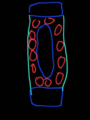
This is how it could look from the side:
Cyan - grease seal
Yellow - the key
Blue - keyway surface
Purple - the wheel
Red - ball bearings

Without that yellow "ramp" to guide balls up I doubt they wouldn't just jam in the corner, but such a tiny piece of material is going to wear in no time... But I'll likely try to add it to my new key. That would be the fourth attempt of making that key. The first didn't block the grease, the second didn't have any provision for balls, the third has no "ramp", but a 90 degree angle in the place shown in the drawing.
since I was a maintenance mechanic I know on large floor drill presses for sure and probably bp's also that the main problems with these systems are caused from turning the motor off with variable position in high speed. then when you turn on your machine it puts force on system parts and motor trying to get to high speed immeadiately. I hated working on these after operators would not turn the variable speed to low before shutting off power(instructions say to do this).
they have some special formed plastic spacer parts that fit over the shaft and key ways, but after all the metal shafts and parts are worn they don't last without problems. best to turn variable speed to low before turning off or bear the headaches it will cause. operators and managers always said they didn't have time to do this, so I was the one who had to pay for their bad habits. all new parts are terrible expensive but needed to work good again.
When this gearbox operates the spindle this is no doubt true, but my gearbox powers table feed. There is no way to "leave it on lowest speed" and wind it up from low to high on every single start. This milling machine is supposed to engage its table feed immediately at correct speed. The manual specifies the feed settings should be made while it operates, but it doesn't mention leaving it at any particular setting.
Also, this machine has two additional features that would make it impossible to use. It has sort of rudimentary "programming" with variously shaped plastic "bricks". You attach those bricks to the table and there is a series of switches that pick them up as table moves. By setting correct bricks at correct positions you can have the feed stop somewhere, engage fast return, feed the other way etc. The manual makes a big deal out of using this feature with the preset feed rates.
This tip should be preached far and wide! They should sell stickers to put on all variable speed machines that say “Turn the variable speed to low before shutting off power”.
I bet his is applicable only to spindle drives. I can't imagine winding a table feed up and down every single time it's engaged.
Perhaps this is the reason for this ball bearing design? They tried to improve the sliding design?
Actually, now that I think about it, there is a much larger variable speed drive for the main spindle. Other than to wind it up and down while it operates the manual also doesn't mention leaving it at any particular setting. Personally I've have it on one setting (around the middle) for most of the time. I think winding it up and down every single time wouod wear it in no time. However, I think this must be a different design than ones you're talking about. It doesn't contradict your experience of course.
