- Joined
- Oct 13, 2014
- Messages
- 9,460
Hi All,
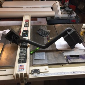
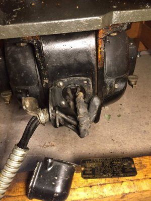
I scored a somewhat historical lathe, a couple of weeks ago. For the most part it is in great shape and only needs a little cleaning, lubrication and new belts. However, in the process of moving it, I had cut the wires to/from the motor and drum switch, I didn't id the wires as I should have (duh) since I thought it would be no biggie to figure out as the motor has a wiring schematic on the spec plate and I have wired several drum switches in the past... I also wanted to replace as much of the old wiring as possible, anyway.
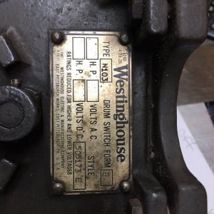
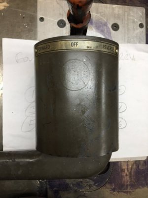
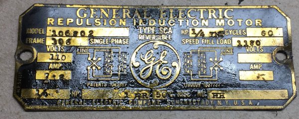
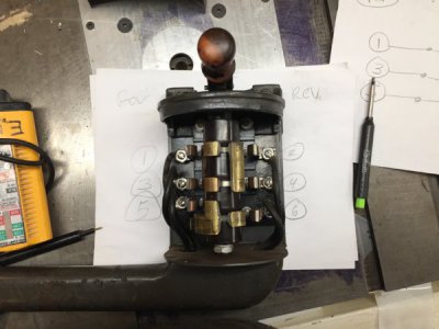
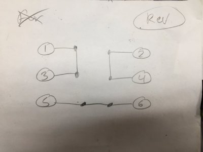
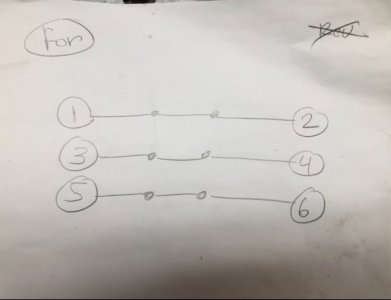
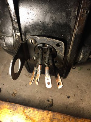
Upon rewiring I have some uncertainties: First, I have no experience with Repulsion-Induction Motors hence, the diagrams on the motor plate are a little unclear to me, as to how it should be wired. Of the 2 diagrams, initially I thought one showed forward status and the other showed reverse, but the diagrams also show different interconnections on the motor, leading me to think the one on the left is for low voltage and the one on the right is for high voltage hook up, although no voltage or amps are stamped on that side of the plate. Further confusion as there are only 4 wires exposed in the motors junction box so none of those interconnects could be readily made, anyway. So I think, the left digram is the one I should follow, but I am somewhat confused buy the "X" pole representing the drum switch. I assume the status shown is "forward" but how would it look in reverse?
So far, I have searched the net and come up with little. One photo of an old paper schematic looks like it is the correct one but is torn and missing the half the circuit (as is always my luck).
I have determined T1 & T2 have continuity as does T3 & T4.
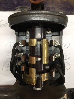
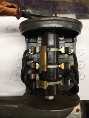
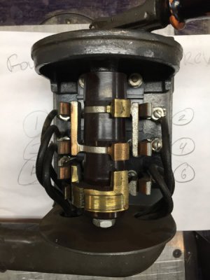
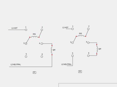
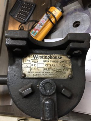
I have determined the switch pole configuration.
I hope someone here can assure me of the correct wiring?
Many Thanks in advance.
Eddy
I scored a somewhat historical lathe, a couple of weeks ago. For the most part it is in great shape and only needs a little cleaning, lubrication and new belts. However, in the process of moving it, I had cut the wires to/from the motor and drum switch, I didn't id the wires as I should have (duh) since I thought it would be no biggie to figure out as the motor has a wiring schematic on the spec plate and I have wired several drum switches in the past... I also wanted to replace as much of the old wiring as possible, anyway.
Upon rewiring I have some uncertainties: First, I have no experience with Repulsion-Induction Motors hence, the diagrams on the motor plate are a little unclear to me, as to how it should be wired. Of the 2 diagrams, initially I thought one showed forward status and the other showed reverse, but the diagrams also show different interconnections on the motor, leading me to think the one on the left is for low voltage and the one on the right is for high voltage hook up, although no voltage or amps are stamped on that side of the plate. Further confusion as there are only 4 wires exposed in the motors junction box so none of those interconnects could be readily made, anyway. So I think, the left digram is the one I should follow, but I am somewhat confused buy the "X" pole representing the drum switch. I assume the status shown is "forward" but how would it look in reverse?
So far, I have searched the net and come up with little. One photo of an old paper schematic looks like it is the correct one but is torn and missing the half the circuit (as is always my luck).
I have determined T1 & T2 have continuity as does T3 & T4.
I have determined the switch pole configuration.
I hope someone here can assure me of the correct wiring?


Many Thanks in advance.
Eddy

