- Joined
- Oct 30, 2019
- Messages
- 225
Today I was working on installation of the engine into my '95 Ranger, and had a moment of pause before reinstalling the old exhaust manifolds. I don't have a great "before" picture of the worse manifold, but one is shown below. The mating faces were rusted to the old gasket badly enough that you could not tell when the gasket stopped and the pitted machined surface began - I couldn't be sure when to stop scraping to remove old gasket, because in some places the texture of the gasket was reflected in the rust pattern of the manifold itself.
I used my insert-based face mill, roughly .010 DOC per pass until the gasket surface was sufficiently flat and clean. The first manifold was just mounted to the table with 123 blocks, trusting that the original machining on the back of the fastener bosses was a sufficient reference.
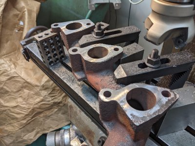
I swept with an indicator prior to starting any cuts - the first two ports (further from the camera, above) measured approximately .005" between them. The 3rd port measured another .020", I believe the manifold may have been warped. However, this did cause me to question whether the back of the fastener bosses were sufficiently coplanar to use them as a reference for fixturing the next manifold.
Here is the finished first manifold, alongside the second:
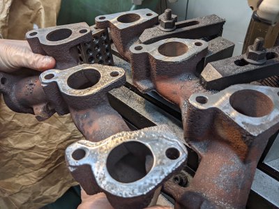
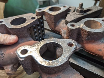
For the second manifold, I decided to machine the back of the fastener bosses with the work clamped face-down to the table first. This would give me a known reference plane that should, on average, be parallel to the unfinished gasket plane:
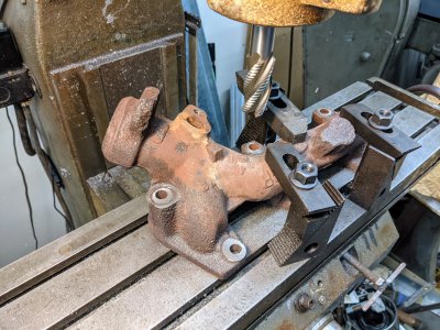
My longest end mill is my 1" roughing end mill, which I needed in order to reach past the manifold features and clamping. On this manifold, 3 of the mounting flanges are approximately 0.5" thick, while the rear is approximately 2.5". I figured as long as I took these down to the same thickness on each side, and knew what the delta was between them - I can mount it face-up on the table later and trust the reference.
Here is where I may have committed a sin of sorts. I don't have any adjustable parallels or machinist jacks short enough to let me build up the ~1.368 inches I needed to support one side of the manifold above the table. I ended up using a stack-up of gage blocks to get the exact spacing needed since the far side was on the 3" side of 123 blocks. I did make sure they were clean, and did not over-tighten them - to minimize the chance of creating raised dimpling in the blocks. These blocks are a used, old, cheap set from ebay - but I do try to show them respect despite what is shown here.
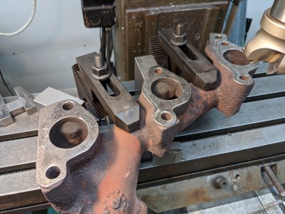
With this more-careful prep and fixturing, and bearing in mind that the first manifold may have been warped -- I was happy to see only .010" material removal (approximately - I don't know that I started at the highest point) needed to clean this side up. This was done in one pass with the same cheap indexable face mill.
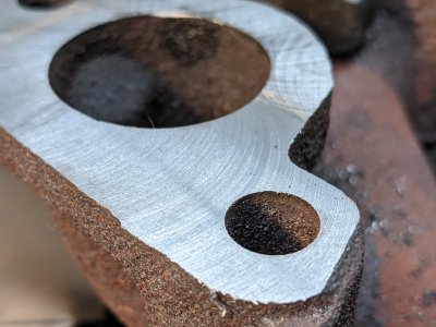
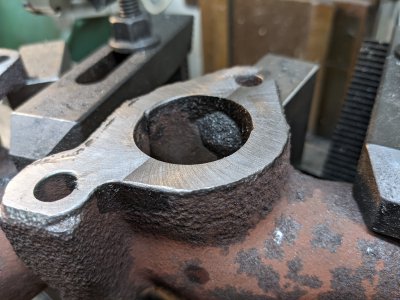
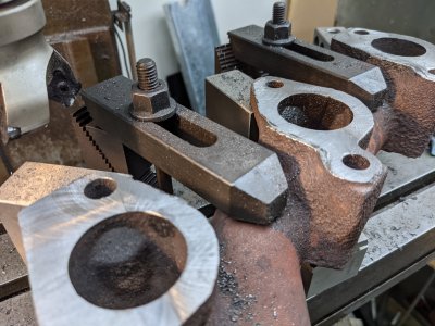
Very happy with the result. This is a Rockwell 21-100 with no power feed, so exact surface finish was a bit of a crapshoot. However, it's clean and flat -- and that is all I needed in this case.
Thanks for reading
I used my insert-based face mill, roughly .010 DOC per pass until the gasket surface was sufficiently flat and clean. The first manifold was just mounted to the table with 123 blocks, trusting that the original machining on the back of the fastener bosses was a sufficient reference.

I swept with an indicator prior to starting any cuts - the first two ports (further from the camera, above) measured approximately .005" between them. The 3rd port measured another .020", I believe the manifold may have been warped. However, this did cause me to question whether the back of the fastener bosses were sufficiently coplanar to use them as a reference for fixturing the next manifold.
Here is the finished first manifold, alongside the second:


For the second manifold, I decided to machine the back of the fastener bosses with the work clamped face-down to the table first. This would give me a known reference plane that should, on average, be parallel to the unfinished gasket plane:

My longest end mill is my 1" roughing end mill, which I needed in order to reach past the manifold features and clamping. On this manifold, 3 of the mounting flanges are approximately 0.5" thick, while the rear is approximately 2.5". I figured as long as I took these down to the same thickness on each side, and knew what the delta was between them - I can mount it face-up on the table later and trust the reference.
Here is where I may have committed a sin of sorts. I don't have any adjustable parallels or machinist jacks short enough to let me build up the ~1.368 inches I needed to support one side of the manifold above the table. I ended up using a stack-up of gage blocks to get the exact spacing needed since the far side was on the 3" side of 123 blocks. I did make sure they were clean, and did not over-tighten them - to minimize the chance of creating raised dimpling in the blocks. These blocks are a used, old, cheap set from ebay - but I do try to show them respect despite what is shown here.

With this more-careful prep and fixturing, and bearing in mind that the first manifold may have been warped -- I was happy to see only .010" material removal (approximately - I don't know that I started at the highest point) needed to clean this side up. This was done in one pass with the same cheap indexable face mill.
Very happy with the result. This is a Rockwell 21-100 with no power feed, so exact surface finish was a bit of a crapshoot. However, it's clean and flat -- and that is all I needed in this case.


Thanks for reading
Last edited:


