- Joined
- Oct 30, 2019
- Messages
- 225
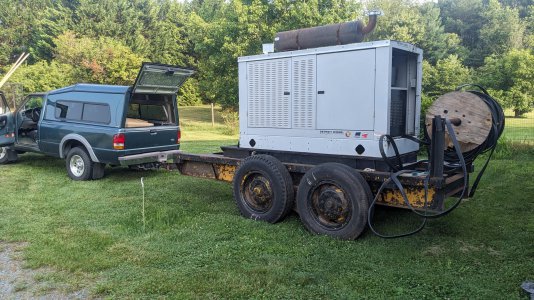
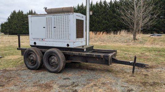
Earlier this year I had the opportunity to buy a non--running 55kw genset for a very good price, after the owner decided they did not want to chase down all the repairs it might need when initial testing and triage showed multiple problems that could be an endless rabbithole.
It is a Detroit Diesel-branded unit, but effectively looks to be a Kohler rebadge
I have worked through the first few layers of issues and eventually figured out that the radiator had multiple leaks... because when the machine first came out of storage and was test run, the space between the fan and radiator was filled with acorns. The fan ground those nuts into the back of the radiator, causing leaks it didn't have when it first came to my property.
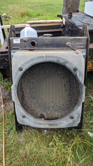
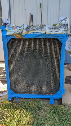
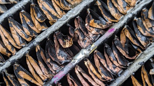
Tons of fins in the circular pathway of the fan are mashed inward by up to 3/8" or 1/2" , with tiny holes in the tubes that were not readily visible except for the general areas of coolant wetness
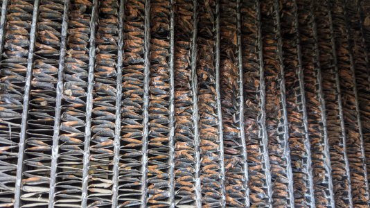
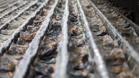
Bummer, because this is about a $900 radiator.
I decided to try and locate the leaks and solder them, so that I could reinstall the radiator and prove the rest of the machine is 100% healthy. Then at a later time I can decide whether to replace the radiator, or whether this might be fine as-is.
The approach I came up with was:
Right out of the gate, there were some dependencies to solve. I don't do much vehicle/radiator work, so I don't have a variety of test plugs to close the inlet/outlet. I could have taken the upper+lower radiator hose off the machine itself, put them on, then just found/made some plug--shaped objects to hoseclamp in the hoses. However, at least one of the radiator hoses has some special components inside (I think stiffeners to keep it from potentially getting drawn flat by the water pump?) and I'd rather leave it attached to the thermostat housing on the machine.
Also, mating surfaces and pressurized components in the sealed system means fewer false positives.
I thought about going to town to see if I could buy test plugs of the right diameters for the inlet/outlet, but then decided to try and make a couple out of hockey pucks.
I had bought a lot of 10 used hockey pucks on ebay back when mounting my air compressor, so that I could turn some mounting pads for it. I chucked one up in the 3-jaw chuck and used a sharp HSS tool to turn it down with an aggressive manual feed rate. Once I got near the desired diameter, I turned a 5 degree taper. This all took maybe 15 minutes?
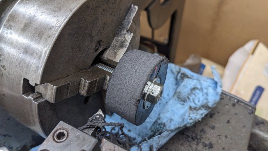
In my box of 3/8-ish hardware I found a cupped washer that I'm pretty sure came off of a strut mount on my '95 Ford Ranger, this seemed perfect to put inside and draw against, to help encourage the rubber to mushroom outward
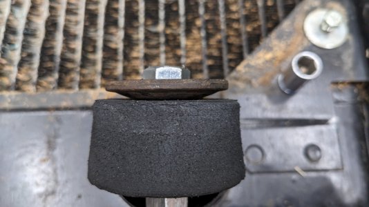
The head of the bolt is on the inside, and a nut+washer are on the outside to draw it tight. The center hole in the plug is 1/64 undersized so that it is a snug fit against the unthreaded portion of the 3/8 bolt
I also made a second one for the other port on the radiator, but for that one I used a 1/2" bolt because this puck already had a 3/8+ hole in the middle from a first prototype at making a compressor mounting pad
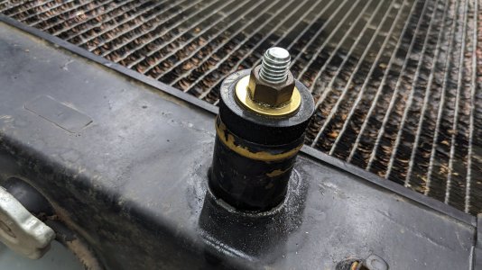
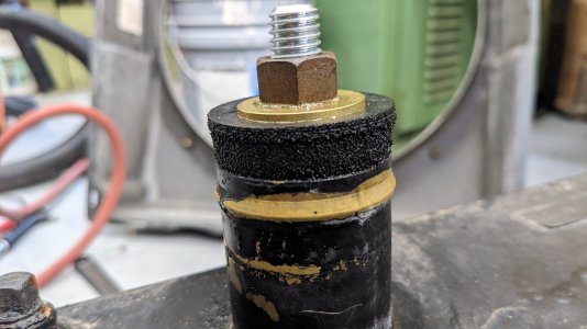
Now, about pressurizing the system... my neighbor is a retired mechanic and does have a radiator/cooling system pressurizing kit/pump. However, I knew that the leaks in the radiator added up to a significant leakage cross-section. The system would not hold pressure long enough for me to locate the leaks, if I used a hand pump. Really what I wanted was flow through the system, but with pressure regulation so that I would not overpressure the system accidentally as I iteratively sealed the leaks up.
So what I did was took the 3/8 bolt from the first test plug, and drilled a 1/8" hole through the middle. I also turned the threads off the end so it somewhat resembled a hose barb
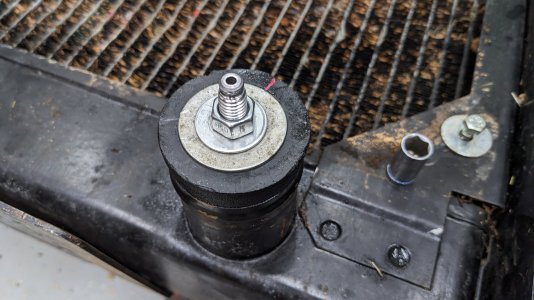
I then hooked up to it a bit of a mess of random components that I had previously used as part of an improvised smoke testing machine to track down exhaust and exhaust leaks on a previous project:
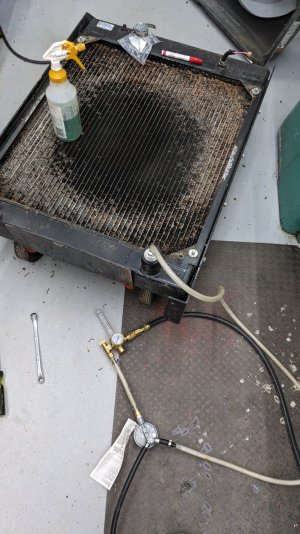
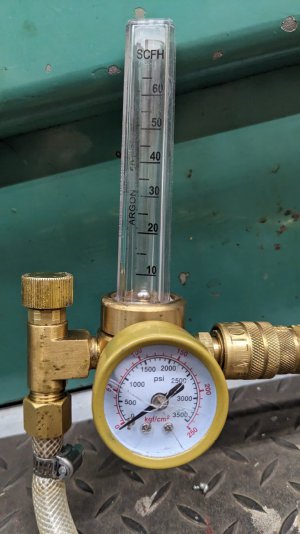
Shop air connects to a welding flow regulator that has the SCFH gauge on it, and a needle valve for adjusting max flow rate. I just needed to replace the cylinder fitting with a shop air male fitting. The flow regulator is not a pressure regulator, however -- so if you hook it up to a sealed system you will ultimately reach shop air pressure or pop something on the way there. So the flow regulator outlet connects to the inlet of a propane regulator from an old bbq grill. This is set to a fixed 1/2 psi, perfect for leak testing systems safely. The regulator was part of a value-engineered product and has an integral splitter on it for feeding two burners, so one of those has its hose plugged off. The other leads to the hose that attaches to the radiator:
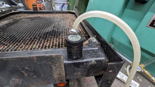
When using this as a smoke tester, this hose goes to a piece of capped pipe that has nichrome wire wrapped around a sock soaked in mineral oil, so that it generates smoke (whose outlet in turn connects to the system under test). Sketchy but I have used it 3-4 times with great success and only one demonstrable fire risk
Now with a source of airflow, I was able to identify 7-8 potential leaks and use a small cutoff wheel (a worn out tiny wheel on a die grinder, I should have gotten the dremel out for precision) to open the hole up a bit and expose a decent surface area for solder to wet
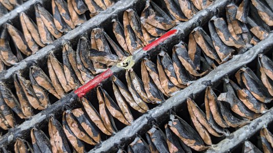
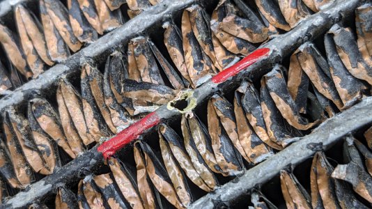
Then used a map gas torch to heat the area and flow solder on. If I had jewelers torches for my OA setup, I would have used that instead because the map and propane torch heads are a huge flame for the 2mm area I am actually trying to heat
Eventually I closed 7 leaks, and the iterative testing brought the flow gauge down to 0 SCFH. Up until the last tiny leak I could find in this approach, the ball was visibly floating -- I could not believe how useful an indicator this was of even the smallest meaningful leaks.
I got the idea for this from a youtube video that showed an actual professional smoke tester, the OTC Leaktamer. It had exactly this style of flow gauge, so I was happy to have a broken/spare regulator in the shop. At some point I should replace this broken high-pressure gauge with one that shows 0-150 psi, the shop air pressures that this really gets used with
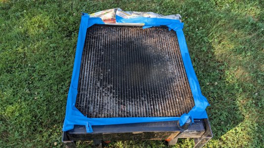
Next was spending a few hours straightening fins with a pick. Not to get it perfect, but to open up the cross section which was blocked to airflow - probably 10% of the radiator was blocked, and another 10% was partially obstructed by the bent fins
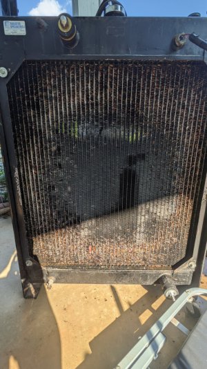
Here is a before/after of roughly the same area on the radiator:
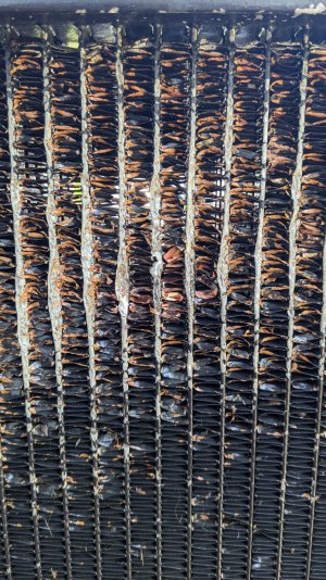
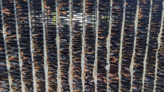
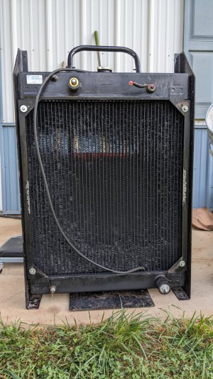
And overall after:

Lastly, pressure testing to see if this holds pressure. Initial indications are yes, but the pressure did drop slightly overnight. The radiator was still too wet from cleaning for me to find a specific leak, so I am repeating the test in the sun today for it to dry out. Also I saw water around the cap bung this morning on top of the radiator, and found a tiny bit of debris that may have been in the sealing surface of the pressure tester - so fingers crossed that maybe there is no leak
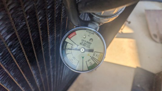
With any luck I'll have a good answer tonight. Worst case there may be a couple tiny leaks remaining, which I hope to identify by water beading tonight
thanks for reading
It is a Detroit Diesel-branded unit, but effectively looks to be a Kohler rebadge

I have worked through the first few layers of issues and eventually figured out that the radiator had multiple leaks... because when the machine first came out of storage and was test run, the space between the fan and radiator was filled with acorns. The fan ground those nuts into the back of the radiator, causing leaks it didn't have when it first came to my property.

Tons of fins in the circular pathway of the fan are mashed inward by up to 3/8" or 1/2" , with tiny holes in the tubes that were not readily visible except for the general areas of coolant wetness


Bummer, because this is about a $900 radiator.
I decided to try and locate the leaks and solder them, so that I could reinstall the radiator and prove the rest of the machine is 100% healthy. Then at a later time I can decide whether to replace the radiator, or whether this might be fine as-is.
The approach I came up with was:
- Bring the radiator into the shop, vacuum all the debris out
- Find a way to seal the inlet and outlet
- Pressurize the radiator
- Look for leaks visually/audibly, mark the locations
- Locate smaller leaks with soap+water, mark the locations
- Prepare/grind and solder each leak
- Pressurize and test with soap+water
- Iterate steps 4-7 until all leaks might be fixed
- Final testing to see if the radiator holds stable pressure for ~12 hours
- Fix additional small leaks found in #9 if needed
Right out of the gate, there were some dependencies to solve. I don't do much vehicle/radiator work, so I don't have a variety of test plugs to close the inlet/outlet. I could have taken the upper+lower radiator hose off the machine itself, put them on, then just found/made some plug--shaped objects to hoseclamp in the hoses. However, at least one of the radiator hoses has some special components inside (I think stiffeners to keep it from potentially getting drawn flat by the water pump?) and I'd rather leave it attached to the thermostat housing on the machine.
Also, mating surfaces and pressurized components in the sealed system means fewer false positives.
I thought about going to town to see if I could buy test plugs of the right diameters for the inlet/outlet, but then decided to try and make a couple out of hockey pucks.
I had bought a lot of 10 used hockey pucks on ebay back when mounting my air compressor, so that I could turn some mounting pads for it. I chucked one up in the 3-jaw chuck and used a sharp HSS tool to turn it down with an aggressive manual feed rate. Once I got near the desired diameter, I turned a 5 degree taper. This all took maybe 15 minutes?

In my box of 3/8-ish hardware I found a cupped washer that I'm pretty sure came off of a strut mount on my '95 Ford Ranger, this seemed perfect to put inside and draw against, to help encourage the rubber to mushroom outward

The head of the bolt is on the inside, and a nut+washer are on the outside to draw it tight. The center hole in the plug is 1/64 undersized so that it is a snug fit against the unthreaded portion of the 3/8 bolt
I also made a second one for the other port on the radiator, but for that one I used a 1/2" bolt because this puck already had a 3/8+ hole in the middle from a first prototype at making a compressor mounting pad


Now, about pressurizing the system... my neighbor is a retired mechanic and does have a radiator/cooling system pressurizing kit/pump. However, I knew that the leaks in the radiator added up to a significant leakage cross-section. The system would not hold pressure long enough for me to locate the leaks, if I used a hand pump. Really what I wanted was flow through the system, but with pressure regulation so that I would not overpressure the system accidentally as I iteratively sealed the leaks up.
So what I did was took the 3/8 bolt from the first test plug, and drilled a 1/8" hole through the middle. I also turned the threads off the end so it somewhat resembled a hose barb

I then hooked up to it a bit of a mess of random components that I had previously used as part of an improvised smoke testing machine to track down exhaust and exhaust leaks on a previous project:

Shop air connects to a welding flow regulator that has the SCFH gauge on it, and a needle valve for adjusting max flow rate. I just needed to replace the cylinder fitting with a shop air male fitting. The flow regulator is not a pressure regulator, however -- so if you hook it up to a sealed system you will ultimately reach shop air pressure or pop something on the way there. So the flow regulator outlet connects to the inlet of a propane regulator from an old bbq grill. This is set to a fixed 1/2 psi, perfect for leak testing systems safely. The regulator was part of a value-engineered product and has an integral splitter on it for feeding two burners, so one of those has its hose plugged off. The other leads to the hose that attaches to the radiator:

When using this as a smoke tester, this hose goes to a piece of capped pipe that has nichrome wire wrapped around a sock soaked in mineral oil, so that it generates smoke (whose outlet in turn connects to the system under test). Sketchy but I have used it 3-4 times with great success and only one demonstrable fire risk
Now with a source of airflow, I was able to identify 7-8 potential leaks and use a small cutoff wheel (a worn out tiny wheel on a die grinder, I should have gotten the dremel out for precision) to open the hole up a bit and expose a decent surface area for solder to wet


Then used a map gas torch to heat the area and flow solder on. If I had jewelers torches for my OA setup, I would have used that instead because the map and propane torch heads are a huge flame for the 2mm area I am actually trying to heat

Eventually I closed 7 leaks, and the iterative testing brought the flow gauge down to 0 SCFH. Up until the last tiny leak I could find in this approach, the ball was visibly floating -- I could not believe how useful an indicator this was of even the smallest meaningful leaks.
I got the idea for this from a youtube video that showed an actual professional smoke tester, the OTC Leaktamer. It had exactly this style of flow gauge, so I was happy to have a broken/spare regulator in the shop. At some point I should replace this broken high-pressure gauge with one that shows 0-150 psi, the shop air pressures that this really gets used with

Next was spending a few hours straightening fins with a pick. Not to get it perfect, but to open up the cross section which was blocked to airflow - probably 10% of the radiator was blocked, and another 10% was partially obstructed by the bent fins

Here is a before/after of roughly the same area on the radiator:


And overall after:

Lastly, pressure testing to see if this holds pressure. Initial indications are yes, but the pressure did drop slightly overnight. The radiator was still too wet from cleaning for me to find a specific leak, so I am repeating the test in the sun today for it to dry out. Also I saw water around the cap bung this morning on top of the radiator, and found a tiny bit of debris that may have been in the sealing surface of the pressure tester - so fingers crossed that maybe there is no leak

With any luck I'll have a good answer tonight. Worst case there may be a couple tiny leaks remaining, which I hope to identify by water beading tonight
thanks for reading
Last edited:

