- Joined
- Feb 5, 2015
- Messages
- 662
I enjoy both woodworking and metalworking, like many of us. For those who work in both crafts, having metalworking capability makes for a better woodworking experience because we can design and produce special-purpose woodworking tools or modify existing ones to suit our purposes. One of my most useful woodworking machines is a radial arm saw and there were many times when using dado blades on the machine that I wished for a radial arm router - especially when making shelving where blind dadoes are common.
I believe I have seen inexpensive kits for making radial arm routers or adapting a radial saw to hold a router. DeWalt has always marketed a threaded collet holder for their radial saw motor to hold router cutters. The machine can be adjusted to any three-dimensional angle (like the human arm from which it was modeled) so that it can serve as a low-speed router, although not a precise one due to the runout of the threaded collet. The machine might work better as a shaper, because of the low speed and because small molding heads can be mounted on the saw arbor directly with less runout. The problem with that implementation is that the radial saw configuration isn't rigid enough for shaper work, at least in my opinion, and it can be a scary experience when a three-blade molding cutter decides to kick back !
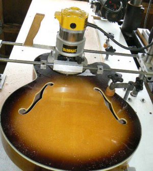
I built this radial router many years ago. There's nothing special about it and, as you will observe from the photos, not much time was spent in the process - whatever materials were on hand drove the design. Despite the simplicity, it has been a useful tool for cabinet work, craft work, some light metalworking and very handy for routing pickups in guitar tops, although I didn't consider that purpose when I built the thing.
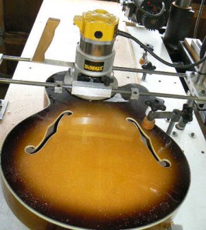
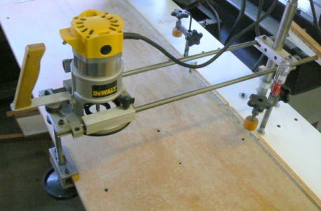
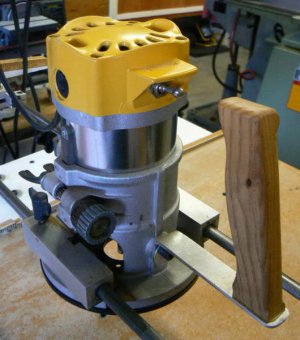
As the name of the device implies, it can be adjusted to any practical angle with respect to the fence - like the radial arm saw that shares the same work table. Metalworkers would consider this device a "skimpy" looking tool, LOL, but for woodworking, it's not bad. High speed routing doesn't require a lot of rigidity to produce the type of work required by the home craftsman - art/craft projects, cabinet work and the like. Here is a photo of the router set up for normal work (perpendicular to the fence):
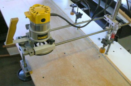
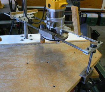
Adjusted for 45 degree angle to the fence:
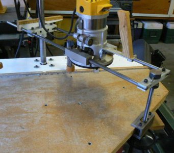
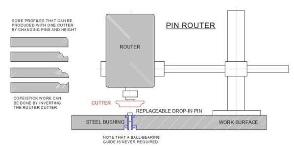
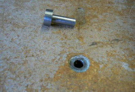
The machine can also be used as a pin router; there is a steel bushing permanently installed in the table surface and custom guide pins can easily be turned as needed for individual tasks. In use, the router is located and locked above the steel bushing so that the spindle is coincident with the bushing. This is easily accomplished by installing a length of 1/4 drill rod in the collet and orienting the machine until the drill rod drops into the steel bushing - after locking the carriage in place, the router motor is lifted out and the drill rod replaced with a cutter. When used as a pin router, the near side support/elevation adjustment mechanism is normally removed. This provides greater freedom for moving the workpiece about the cutter at some sacrifice of rigidity (fortunately, rigidity isn't critical for most tasks).
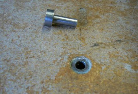
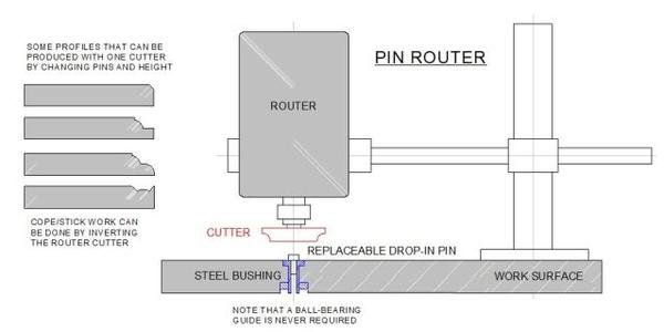
Pin routers are versatile tools that allow contouring any profile that a router cutter - or any combination of cutters that happen to be on hand - can produce WITHOUT a ball-bearing guide or a fence. The guide for the workpiece doesn't rotate so there is no possibility of burning - even soft woods like bass or poplar - except from the cutting surfaces. The technique is even more useful for pattern routing which is used often in industrial woodworking shops.
Unlike the fixed diameters of ball-bearing guided cutters, tool offset can be adjusted easily by turning different pin diameters (or turning a bushing for an existing pin) - a five minute task in any small engine lathe. It doesn't take long to accumulate a collection of various pin diameters. I'm surprised at how much money is spent on home woodworking equipment - especially routers - but only one out of five hundred home shops includes a pin router - the most versatile edge-processing tool I can think of.
There's no great incentive for machinery manufacturers to introduce pin routers to the home shop since the lucrative market for ball-bearing guided, brazed-carbide router cutters would disappear. (I think "Grizzly" introduced a pin router two or three years ago. As I recall, it was a small industrial model, not home-shop oriented.)
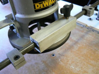
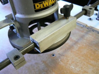
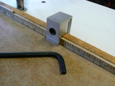
The router can be locked in any position along the slide and also has travel stops, like a mill table. Here are photos of the slide locks and the travel limit stops that clamp to the fence.
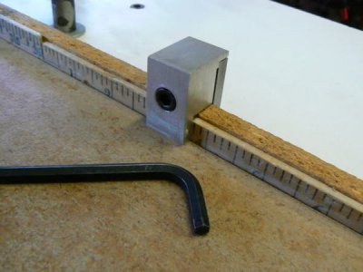
When routing long lengths of work, the workpiece is generally passed along/against the fence. If mortises are being cut, the travel of the workpiece needs to be limited so there are two limit stops that clamp to the fence (the devices have internal springs so that they self release when the cap screw is loosened).
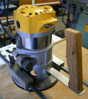
The router travels on 1/2 diameter ground steel shafts inside oilite bushings that were line-reamed to size after being press-fitted into the router carriage blocks. There are two one inch long bushings in each carriage block and the space between them is packed with grease. The router baseplate had to be attached to a right-angle plate and milled flat on each side for attaching the carriage blocks. (The router baseplate is a casting and was not machined on the top side except where mounted to the elevating mechanism.)
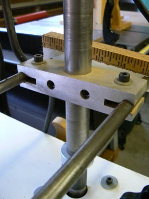
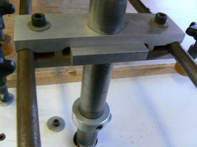
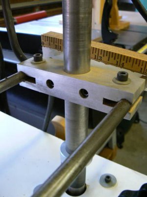
The end supports for the 1/2 inch shafts are aluminum, bored and reamed for the shafts and then split. Socket head cap screws tighten the split blocks securely to the shafts. The rear support slides up and down on a vertical shaft and can be locked at any point. The vertical shaft is a short length of one inch pipe, welded to a pipe flange (the face of the flange faces "up" and mounts to the underside of the table) and then turned in the lathe.
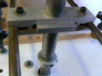
The vertical shaft was aligned perpendicular to the table by carefully measuring the misalignment in four places, then making shims for the four mounting holes in the pipe flange, beneath the table. A few moments with the calculator was required to determine the shim thicknesses and one shim required fine-tuning, LOL ! A sliding collar, positioned underneath the rear support, allows the complete router assembly to be rotated freely when the split block is loosened. These are photos of the rear support from different aspects:
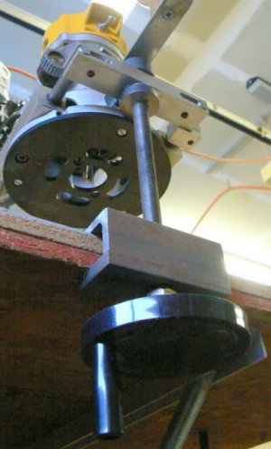
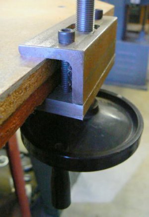
This is the lower section of the front support mechanism, it can be clamped to the front edge of the table after adjusting the desired angle with the fence. The front support includes a threaded lead screw so that it can be adjusted to match the height of the rear support and then locked into place.
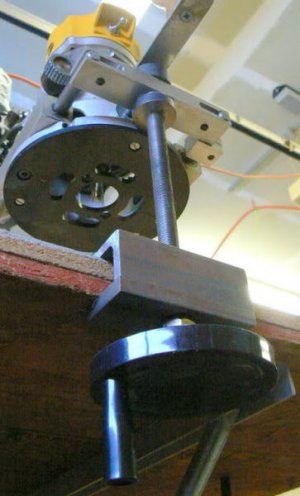
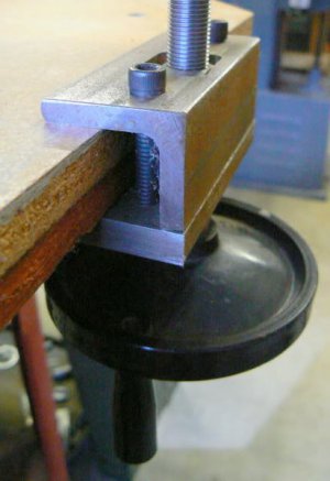
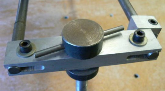
Here is the upper section of the front support, to which the guide shafts are attached:
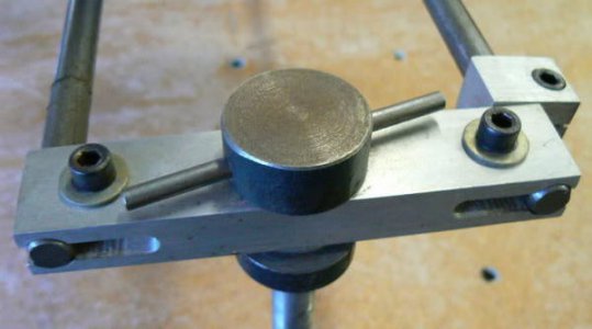
The various split clamps were milled to split them, rather than the conventional practice of sawing a relief slot. For the life of me I cannot recall why I did that, LOL. I don't have any slitting saws large enough to make those cuts in either milling machine but the slits could have been done in a flash on any of the bandsaws (or even on the table saw using a tenon jig and a carbide blade). It remains a mystery to me.
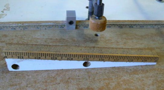
I tried several different methods for adjusting the height of the router to make sure that it is the same distance from the table, front-to-rear. Finally, I hit on this very simple measuring tool which is simply a piece of yardstick glued to a scrap that has been cut to 5.7 degrees, which gives a slope of 10:1. In use, the rear support is adjusted to the desired height and the front support adjusted approximately to the right height.
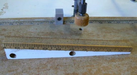
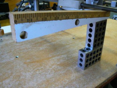
The measurement tool is placed on top of a 1-2-3 block on the radial saw table and slid along the block until it is tangent to one of the 1/2 diameter shafts, noting the point on the measurement tool that touches the shaft. Moving the tool and the 1-2-3 block to the front of the table, the leadscrew handwheel is adjusted until the same 1/2 diameter shaft is tangent to the measurement tool at the same point that touched the shaft at the rear of the table.
This adjustment sets the travel of the router parallel with the work surface (the radial arm saw table). Precise depth adjustments are made in the usual manner with the geared height adjustment knobs on the router body. The router in these photos is a 1-1/2 hp DeWalt which was not the original choice. The shaft spacing and diameter were determined originally by an imported plunge router. The plunge router was modified so that the guide rod holes were bored for oilite bushings.
I wasn't happy with the performance of the imported router - it was top-heavy and required a LOT of pressure to lower the router motor to the stops. Replacing the springs with lighter ones reduced the required pressure but then caused the machine to occasionally bind on the guide rods. I eventually gave up on modifying the plunge router and traded for the smaller DeWalt which does a fine job and has adequate horsepower for my needs.
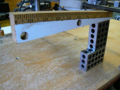
The purpose of the 10:1 slope on the measurement tool is that any measurement division on the yardstick is divided by 10 for comparison purposes. For example, if the measurement tool is adjusted tangent to the shaft at the rear of the table and then adjusted tangent to the shaft at the front of the table, then the difference in height is the difference between the two readings divided by 10. If the tangent difference, front-to-rear, is 1/16 of an inch, then the actual difference in height is .006 inches.
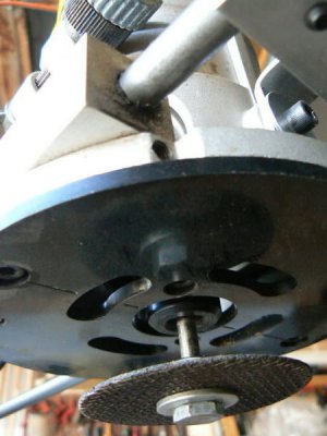
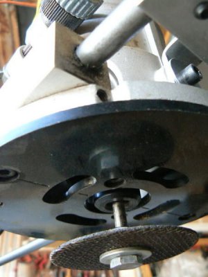
It's a quick method for making a fairly precise adjustment - it is not particularly difficult to align the front to rear travel parallel with the table within .003 inches, more than precise enough for woodworking purposes. However, I use the router for metalworking chores as well. It's particularly useful with an abrasive cut-off wheel for roughing out lathe tools and similar chores. The following photo is "posed" - the cut-off wheel protrudes much further from the router collet than desired and there is no "slinger" (a tin can lid with a collar soft-soldered to it) that is normally mounted on the arbor next to the collet and prevents abrasive dust from being ingested by the router. (The router base must be removed to properly mount the slinger and the cut-off wheel, I didn't want to take the time to do so just to take a photograph.)
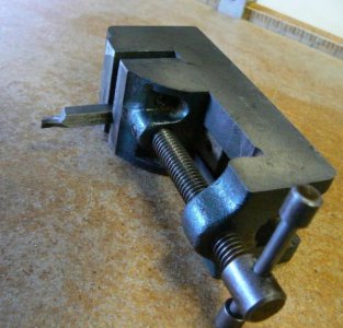
The router can be clamped and small workpieces passed through the cut-off wheel, although NOT by hand. There is an obvious safety hazard with fingers located close to the abrasive wheel not to mention that the work gets HOT ! Small work is usually secured in a small drill press vise or toolmaker's vise and guided through the wheel. This is an example (although not a real pretty one): a little trepanning tool clamped in a small drill press vise was roughed out in about a minute using the cut-off wheel, then finished with several diamond laps.
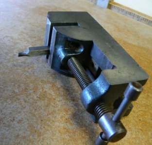
Larger workpieces can be clamped to the radial arm saw table and the router guided along the parallel shafts to make a cut or grind a surface. This is substantially the same process as an abrasive chop saw except that small work is hand-guided. It's helpful to secure a shop-vac hose close to the work to pick up grinding dust - makes the cleanup chore a little easier. Mounted points can be installed in the router for sharpening chisels, lathe tools and the like with a fair degree of precision.
The mechanism is convenient for light routing on aluminum, especially corner rounding and chamfering. The router is permanently attached to an inexpensive universal motor controller so that the speed can be adjusted relative to the diameter of the cutter and the material of the work. If the work is clamped down, it is possible to plunge and slot aluminum sheet metal with the radial router although I don't normally do this unless the workpiece won't fit on my mill table.
I don't have any drawings of the radial router; it was one of those projects that never made it onto a sheet of paper. Like many other projects that we make, the process involved designing/machining "on the fly" using whatever materials were available. If I were to do this over, changes would be made but nothing major - the thing works OK. I need to wipe down the shafts fairly often if a cut-off wheel is used (I keep a roll of toilet paper handy in the shop for wiping off abrasive particles from any of the machinery).
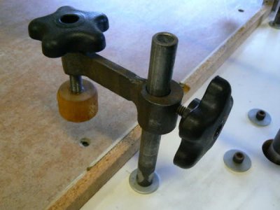
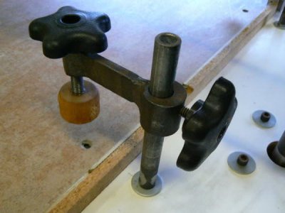
There are several work clamps built onto the table, they can pivot from side to side and are adjustable for clamping height. These are just scraps salvaged from under the horizontal bandsaw, welded and machined as required. The clamping surfaces are pieces of ash, turned on the lathe and then epoxied to the clamp screw.
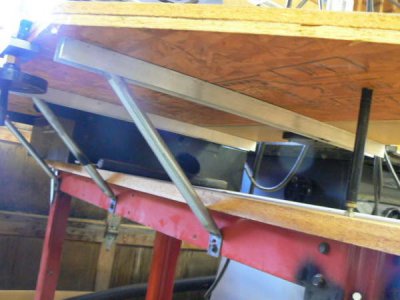
The router shares the same table as the DeWalt radial arm saw. At first, I provided four adjustable (threaded) struts underneath the table to level it but this wasn't successful. The table sagged in several places and couldn't be leveled well enough for precise cabinet work. I made a new top by gluing up two pieces of wafer board (the "grain" - such as it is) was oriented ninety degrees to each other. Then I mounted four lengths of 2 x 2 aluminum channel across the underside of the top. The channels were drilled and tapped for 10-32 threads and the top was attached with socket head cap screws and large washers, into counterbored holes.
At the end of the aluminum channels, braces made from one inch conduit were attached. These have slotted mounting holes so that the top can be nudged into a level condition and then the braces securely tightened. Almost forgot: before doing these things, I tack welded all of the sheet metal interfaces of the table on which the saw and the router are mounted. (It was an inexpensive Sears utility table, purchased for another purpose originally.) After welding all of the interfaces and adding braces to the legs, the structure is quite rigid.
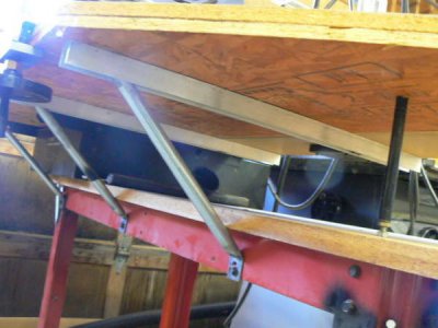
The original four struts were re-used, one can be seen in the foreground; they were helpful in leveling the table since they have a threaded push-pull arrangement that makes adjustment simple. I wish that I would have painted the entire contraption but then I ALWAYS wish that !
I believe I have seen inexpensive kits for making radial arm routers or adapting a radial saw to hold a router. DeWalt has always marketed a threaded collet holder for their radial saw motor to hold router cutters. The machine can be adjusted to any three-dimensional angle (like the human arm from which it was modeled) so that it can serve as a low-speed router, although not a precise one due to the runout of the threaded collet. The machine might work better as a shaper, because of the low speed and because small molding heads can be mounted on the saw arbor directly with less runout. The problem with that implementation is that the radial saw configuration isn't rigid enough for shaper work, at least in my opinion, and it can be a scary experience when a three-blade molding cutter decides to kick back !
I built this radial router many years ago. There's nothing special about it and, as you will observe from the photos, not much time was spent in the process - whatever materials were on hand drove the design. Despite the simplicity, it has been a useful tool for cabinet work, craft work, some light metalworking and very handy for routing pickups in guitar tops, although I didn't consider that purpose when I built the thing.

As the name of the device implies, it can be adjusted to any practical angle with respect to the fence - like the radial arm saw that shares the same work table. Metalworkers would consider this device a "skimpy" looking tool, LOL, but for woodworking, it's not bad. High speed routing doesn't require a lot of rigidity to produce the type of work required by the home craftsman - art/craft projects, cabinet work and the like. Here is a photo of the router set up for normal work (perpendicular to the fence):

Adjusted for 45 degree angle to the fence:

The machine can also be used as a pin router; there is a steel bushing permanently installed in the table surface and custom guide pins can easily be turned as needed for individual tasks. In use, the router is located and locked above the steel bushing so that the spindle is coincident with the bushing. This is easily accomplished by installing a length of 1/4 drill rod in the collet and orienting the machine until the drill rod drops into the steel bushing - after locking the carriage in place, the router motor is lifted out and the drill rod replaced with a cutter. When used as a pin router, the near side support/elevation adjustment mechanism is normally removed. This provides greater freedom for moving the workpiece about the cutter at some sacrifice of rigidity (fortunately, rigidity isn't critical for most tasks).

Pin routers are versatile tools that allow contouring any profile that a router cutter - or any combination of cutters that happen to be on hand - can produce WITHOUT a ball-bearing guide or a fence. The guide for the workpiece doesn't rotate so there is no possibility of burning - even soft woods like bass or poplar - except from the cutting surfaces. The technique is even more useful for pattern routing which is used often in industrial woodworking shops.
Unlike the fixed diameters of ball-bearing guided cutters, tool offset can be adjusted easily by turning different pin diameters (or turning a bushing for an existing pin) - a five minute task in any small engine lathe. It doesn't take long to accumulate a collection of various pin diameters. I'm surprised at how much money is spent on home woodworking equipment - especially routers - but only one out of five hundred home shops includes a pin router - the most versatile edge-processing tool I can think of.
There's no great incentive for machinery manufacturers to introduce pin routers to the home shop since the lucrative market for ball-bearing guided, brazed-carbide router cutters would disappear. (I think "Grizzly" introduced a pin router two or three years ago. As I recall, it was a small industrial model, not home-shop oriented.)

The router can be locked in any position along the slide and also has travel stops, like a mill table. Here are photos of the slide locks and the travel limit stops that clamp to the fence.

When routing long lengths of work, the workpiece is generally passed along/against the fence. If mortises are being cut, the travel of the workpiece needs to be limited so there are two limit stops that clamp to the fence (the devices have internal springs so that they self release when the cap screw is loosened).

The router travels on 1/2 diameter ground steel shafts inside oilite bushings that were line-reamed to size after being press-fitted into the router carriage blocks. There are two one inch long bushings in each carriage block and the space between them is packed with grease. The router baseplate had to be attached to a right-angle plate and milled flat on each side for attaching the carriage blocks. (The router baseplate is a casting and was not machined on the top side except where mounted to the elevating mechanism.)

The end supports for the 1/2 inch shafts are aluminum, bored and reamed for the shafts and then split. Socket head cap screws tighten the split blocks securely to the shafts. The rear support slides up and down on a vertical shaft and can be locked at any point. The vertical shaft is a short length of one inch pipe, welded to a pipe flange (the face of the flange faces "up" and mounts to the underside of the table) and then turned in the lathe.
The vertical shaft was aligned perpendicular to the table by carefully measuring the misalignment in four places, then making shims for the four mounting holes in the pipe flange, beneath the table. A few moments with the calculator was required to determine the shim thicknesses and one shim required fine-tuning, LOL ! A sliding collar, positioned underneath the rear support, allows the complete router assembly to be rotated freely when the split block is loosened. These are photos of the rear support from different aspects:


This is the lower section of the front support mechanism, it can be clamped to the front edge of the table after adjusting the desired angle with the fence. The front support includes a threaded lead screw so that it can be adjusted to match the height of the rear support and then locked into place.


Here is the upper section of the front support, to which the guide shafts are attached:

The various split clamps were milled to split them, rather than the conventional practice of sawing a relief slot. For the life of me I cannot recall why I did that, LOL. I don't have any slitting saws large enough to make those cuts in either milling machine but the slits could have been done in a flash on any of the bandsaws (or even on the table saw using a tenon jig and a carbide blade). It remains a mystery to me.
I tried several different methods for adjusting the height of the router to make sure that it is the same distance from the table, front-to-rear. Finally, I hit on this very simple measuring tool which is simply a piece of yardstick glued to a scrap that has been cut to 5.7 degrees, which gives a slope of 10:1. In use, the rear support is adjusted to the desired height and the front support adjusted approximately to the right height.

The measurement tool is placed on top of a 1-2-3 block on the radial saw table and slid along the block until it is tangent to one of the 1/2 diameter shafts, noting the point on the measurement tool that touches the shaft. Moving the tool and the 1-2-3 block to the front of the table, the leadscrew handwheel is adjusted until the same 1/2 diameter shaft is tangent to the measurement tool at the same point that touched the shaft at the rear of the table.
This adjustment sets the travel of the router parallel with the work surface (the radial arm saw table). Precise depth adjustments are made in the usual manner with the geared height adjustment knobs on the router body. The router in these photos is a 1-1/2 hp DeWalt which was not the original choice. The shaft spacing and diameter were determined originally by an imported plunge router. The plunge router was modified so that the guide rod holes were bored for oilite bushings.
I wasn't happy with the performance of the imported router - it was top-heavy and required a LOT of pressure to lower the router motor to the stops. Replacing the springs with lighter ones reduced the required pressure but then caused the machine to occasionally bind on the guide rods. I eventually gave up on modifying the plunge router and traded for the smaller DeWalt which does a fine job and has adequate horsepower for my needs.

The purpose of the 10:1 slope on the measurement tool is that any measurement division on the yardstick is divided by 10 for comparison purposes. For example, if the measurement tool is adjusted tangent to the shaft at the rear of the table and then adjusted tangent to the shaft at the front of the table, then the difference in height is the difference between the two readings divided by 10. If the tangent difference, front-to-rear, is 1/16 of an inch, then the actual difference in height is .006 inches.
It's a quick method for making a fairly precise adjustment - it is not particularly difficult to align the front to rear travel parallel with the table within .003 inches, more than precise enough for woodworking purposes. However, I use the router for metalworking chores as well. It's particularly useful with an abrasive cut-off wheel for roughing out lathe tools and similar chores. The following photo is "posed" - the cut-off wheel protrudes much further from the router collet than desired and there is no "slinger" (a tin can lid with a collar soft-soldered to it) that is normally mounted on the arbor next to the collet and prevents abrasive dust from being ingested by the router. (The router base must be removed to properly mount the slinger and the cut-off wheel, I didn't want to take the time to do so just to take a photograph.)

The router can be clamped and small workpieces passed through the cut-off wheel, although NOT by hand. There is an obvious safety hazard with fingers located close to the abrasive wheel not to mention that the work gets HOT ! Small work is usually secured in a small drill press vise or toolmaker's vise and guided through the wheel. This is an example (although not a real pretty one): a little trepanning tool clamped in a small drill press vise was roughed out in about a minute using the cut-off wheel, then finished with several diamond laps.

Larger workpieces can be clamped to the radial arm saw table and the router guided along the parallel shafts to make a cut or grind a surface. This is substantially the same process as an abrasive chop saw except that small work is hand-guided. It's helpful to secure a shop-vac hose close to the work to pick up grinding dust - makes the cleanup chore a little easier. Mounted points can be installed in the router for sharpening chisels, lathe tools and the like with a fair degree of precision.
The mechanism is convenient for light routing on aluminum, especially corner rounding and chamfering. The router is permanently attached to an inexpensive universal motor controller so that the speed can be adjusted relative to the diameter of the cutter and the material of the work. If the work is clamped down, it is possible to plunge and slot aluminum sheet metal with the radial router although I don't normally do this unless the workpiece won't fit on my mill table.
I don't have any drawings of the radial router; it was one of those projects that never made it onto a sheet of paper. Like many other projects that we make, the process involved designing/machining "on the fly" using whatever materials were available. If I were to do this over, changes would be made but nothing major - the thing works OK. I need to wipe down the shafts fairly often if a cut-off wheel is used (I keep a roll of toilet paper handy in the shop for wiping off abrasive particles from any of the machinery).
There are several work clamps built onto the table, they can pivot from side to side and are adjustable for clamping height. These are just scraps salvaged from under the horizontal bandsaw, welded and machined as required. The clamping surfaces are pieces of ash, turned on the lathe and then epoxied to the clamp screw.

The router shares the same table as the DeWalt radial arm saw. At first, I provided four adjustable (threaded) struts underneath the table to level it but this wasn't successful. The table sagged in several places and couldn't be leveled well enough for precise cabinet work. I made a new top by gluing up two pieces of wafer board (the "grain" - such as it is) was oriented ninety degrees to each other. Then I mounted four lengths of 2 x 2 aluminum channel across the underside of the top. The channels were drilled and tapped for 10-32 threads and the top was attached with socket head cap screws and large washers, into counterbored holes.
At the end of the aluminum channels, braces made from one inch conduit were attached. These have slotted mounting holes so that the top can be nudged into a level condition and then the braces securely tightened. Almost forgot: before doing these things, I tack welded all of the sheet metal interfaces of the table on which the saw and the router are mounted. (It was an inexpensive Sears utility table, purchased for another purpose originally.) After welding all of the interfaces and adding braces to the legs, the structure is quite rigid.

The original four struts were re-used, one can be seen in the foreground; they were helpful in leveling the table since they have a threaded push-pull arrangement that makes adjustment simple. I wish that I would have painted the entire contraption but then I ALWAYS wish that !


