QCTP Base Question

q20v

Registered
Registered
Joined
Dec 12, 2012
Messages
109
A 6" vise is overkill for a RF45 style mill. A 4" is more appropiate for that size mill & IMO 5" max. I have a 5" GMT vise on my PM45 & it's slightly too big. Not enough Y axis travel to make use of the 5" full capacity. Better to save your money rather than getting something too big & most importantly the weight. I take my vise of the table quite often, a 6" is still light enough for me to be carried by hand but I'm glad I have a 5". I also have a 4" vise as well. I prefer the 5" though.

But those GMT 6" Premium vises are pretty nice. I'd love to have one but don't need one on my current mill. But if you plan on upgrading to a full size knee mill in the future than the 6" will be perfect.


Here's what the 5" looks like on my mill.
Img_1921.jpg


I couldn't even complete this cut without my bellows & DRO scale getting in the way. Not enough Y travel & the 5" vise is not even maxed out.
Img_7597_zpscb8b5dd7.jpg


Here's what a 6" vise looks like on another PM45 (gt40's)
View attachment 253544
7564.png

7565.png

7566.png
 
Thanks for the quick reply, Frank. I appreciate the input.
 
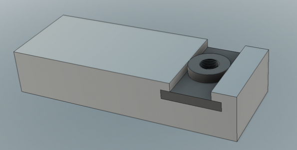
And as with any T-nut modification, just make sure your bolt or stud, whatever, doesn't protrude past the bottom of your T-nut.

-frank
 
Also make sure the cylinder portion does not clamp to the bottom of the tool post when tightened. Make sure you can see light between them.
 
Thanks for the reminders, guys. Weather permitting, hopefully by the end of the week I'll have the QCTP ready. I've been looking forward to this day for a long time!
 
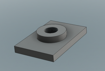
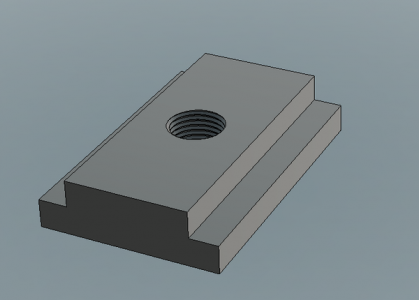
Just a thought but the square style would be more rigid than the round one.
 
Just a thought but the square style would be more rigid than the round one.

I respectfully disagree, the bottom of the toolpost should not even touch the top of the round (or rectangular) nut. It should tighten down against the flat top surface of the componnd, just as Bob discribes in post #5. JR49
 
Hunh?

JR49: My comment refers to the square style T nut shown in the top photo of q20v's post being more rigid than the round one in the lower photo. How does that conflict with what Bob or you wrote?
It has already been written above so it should go without saying again that either T nut style must not bottom against the tool post or it would not clamp to the compound.
As so for what Frank wrote about the bolt not protruding beyond the nut.
Finally, either style will work. But if we are looking for a difference between the two, the square one is more rigid.
 
Last edited:
The Autodesk Fusion software I used to model the two styles does come with an FEA (Finite Element Analysis) package. Tonight after the kids are put to bed I'll apply a load to simulate the tool post being tightened, and measure deflection in the center. I can compare the two designs this way.

Once the tool post handle is tightened and the tool post is clamped between the handle and compound, friction between the mating parts prevents the tool post from sliding / rotating when cutting forces are introduced. Provided the 'round' design doesn't flex to the point that contact is made between the base and tool post when the handle is tightened (ultimately limiting the amount of friction holding everything in place), then I suppose both designs would be okay from a functional standpoint.

Worst case, if the round design does end up flexing a bit more than the square design, I can machine a bit more off the overall thickness to ensure a gap is present between the base / tool post once the handle is tightened. I can also check the stress levels in the FEA results to make sure the base isn't being over stressed. Definitely way way overkill for something like this, but it exercises the brain and is fun.

Thanks again for everyone's input. I'll be certain to share the results of the analysis when I'm done.
 
Back
Top