- Joined
- Feb 1, 2015
- Messages
- 9,995
It is time to winterize the outboard again. One of the tasks involves draining the gear lube out of the lower unit and filling with fresh lube. Outboards usually have two or three ports, one at the bottom for draining and a second at the top for for venting. The filling procedure involves opening the vent and adding lube through the drain until lube begins to flow out the vent. At that point, the vent is closed and the fill tube removed and the drain plug installed.
Commercial lube pumps are available for this process for about $15 and over the years, I have owned several. They are made of plastic and typically only last a year or two before the plastic swells and the pump becomes unusable. I spent an afternoon on the internet looking for a more permanent solution to no avail so I decided to make my own. All materials came from my parts and scrap collection.
For the pump body, I chose an old air spring from some long gone vehicle. The spring was 8" long and had an internal bore of 5/8" which would give me about one ounce of lube per stroke. After making a small cut to relieve the gas pressure, I cut the ends off the cylinder and pulled the piston assembly out. Next, I cut the piston and coupling off the ends of the piston rod, leaving me with a 5/16" shaft. The shaft was turned to .191" on one end and threaded for a 1/2" with 10-32 by 5/16" long thread. The other end was threaded with a 5/16-18 by 1/2" thread.
A new piston was turned to .625" diameter from some 3/4" aluminum bar and a a groove cut to accept a 5/8" o.d. by 3/32" wide Buna-N O ring. Usually, I would make a detailed drawing of the part but in this case, I just winged it, turning until it looked and felt right. A .450 diameter groove gave the good fit for a tight seal without undo friction.
Next, threaded one end of the cylinder for 1/4 NPT. I left the other end plain as I didn't want to damage the O ring when I inserted the piston. I turned an end cap for an light press fit on the cylinder from a piece of Nylon bar. A 1/4 NPT x 1/8" NPT brass bushing was fitted to the cylinder.
The next step was to make the valve assembly for the pump. I decided to use two 5/16" ball bearings for the valves. For the valve springs, I selected one from my spring collection. From its shape, it appear to be from a compression spring for an electric motor brush. It had a 1/4" i.d. and .014" wire. I determined that the spring force was around 2 oz. for what would be a typical compression in the valve.
The valve body was made from a piece of 3/4" aluminum plate from the scrap box. The valve body was designed with the inlet and outlet both on one end and a piece of 1/4" plate containing the coupling to the cylinder on the other. The cylinder end was machined first with .156" through holes for the fluid passage drilled first. This was followed by boring one hole to .625" depth and milling a connecting pocket .125" deep with an 11/32" end mill. A 19/64" ball end mill, taken to a depth of .700" was used to cut the valve seat. The final seat was later formed by pressing the 5/16" bearing into the seat. Six holes for mounting the cover plate were drilled and tapped for 4-40 threads.
The valve body was flipped and two 11/32" holes were bored, one to .625" depth for the second valve seat and the second to .458" depth on preparation for tapping the 1/8" NPT hole. The valve hole was cut to .700" depth with the 19/64" ball end mill. The two holes were then tapped for 1/8" NPT. This completed the machining of the valve body. As a final step, a 5/16" ball was then firmly pressed in to form the valve seats.
The 1/4" cover plate was cut to size and the six .110" through holes for the mounting screw were drilled. An 11/32" hole for the 1/8" NPT plug was cut with the previously used end mill and tapped. A hole concentric to the valve hole was drilled, tapped and countersunk for 10-32 UNF for the purpose of a restraining pin for the valve spring completing the machining of the cover plate.
In retrospect. it would have been easier to move the 1/8" NPT hole in the cover plate to one side about .1" to provide more room for the restraining pin. Also, increasing the slot width and depth in the valve body would have simplified construction. One of the pitfalls arising from not doing complete modeling of the assembly.
The restraining pin was made from a flat head screw. The threads were removed from all but 1/4" using the lathe. Two nuts were used to provide for mounting the screw in the lathe. Nuts seldom have threads concentric with the hex feature. I could have made a custom bushing for this purpose but it was more expedient to just use a file to remove the threads. Again a non critical part; the threads were removed to prevent the spring from hanging up.
Two 1/8" MPT x 1/4 hose barbs were used for the connections to the outside world. One was counterbored to provide a seat for a valve spring.
The final bit of machining was to make a handle for the pump rod. A piece of scrap aluminum was used to make the handle, no particular size in mind, just what looked good. All six sides were milled to clean them up and a through hole frilled and tapped for 10-32 UNF. I could have written a program to cut the curves on the CNC mill but that seemed like a lot of work for a non critical part. I used a shoeing rasp to rough out the profile followed by progressively finer files, a piece of cloth backed sanding belt and finished with some 130 grit emery cloth.
Next was assembly of all the parts. The 1/4" NPT bushing was installed in cylinder, followed by a brass 1/8" NPT short nipple. One end of the nipple had to be shortened to not be proud of the end of the cover plate (see lessons learned three paragraphs up). The restraining pin was fitted in the cover plate. A 5/16" ball followed by the spring were inserted in the valve housing and the cover plate was fastened with six 4-40 screws. A 5/16" ball and spring were inserted in outlet valve, followed by the counterbored hose barb and the second hose barb inserted in the other hole.
The piston was place on the piston rod and secured with a 10-32 nut. The O ring was coated with oil and the assembly slid into the cylinder bore. The end cap was pressed in place and the handle screwed on the piston rod, completing the assembly.
I had tested the valve design using air and found the balls would unseat with less than 2 psi so I felt fairly confident in my design. For a test, I hooked some pvc tubing and tried pumping some way oil. The inlet valve worked fine, drawing the way oil into the pump but on the discharge stroke, the pump locked up. I was puzzled by this behavior as all the fittings and tubing were clear. Closer investigation show that the outlet valve would permit a small amount of oil to flow before locking up, about 1/2" of stroke. If I paused for a few seconds, could repeat the cycle. The light bulb came on; the ball was being push into seating on the bottom of the hose barb. I removed the barb and cut two cross slots in the threaded end which solved the problem.
I used the fill nozzle from the old commercial pump as it threads into the fill port and has a swivel joint. to facilitate installing and removal. I added a brass fitting to the intake hose t help keep it below the surface of the lube.
I changed the gear lube today and the pump did the job. It took about twenty seconds to fill the pump body due to the viscosity of the gear lube and the comparatively lower pressure difference (maximum 15 psi). The discharge stoke develops considerably higher pressure and so took less than two seconds. The whole refill process took less than five minutes with no mess. All in all, a great success.
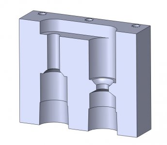
Cut away of the valve body
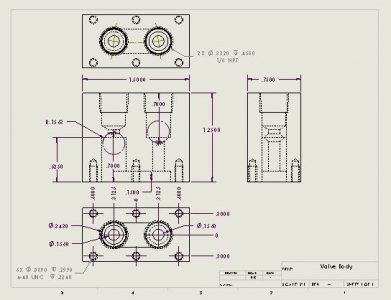
Detailed drawing of the valve body.
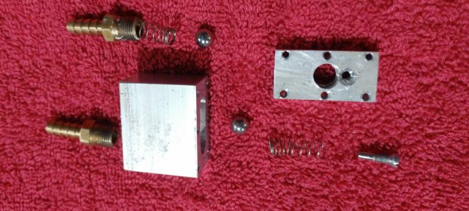
The components of the valve assembly
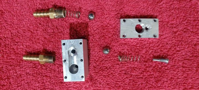
Another view of the valve body
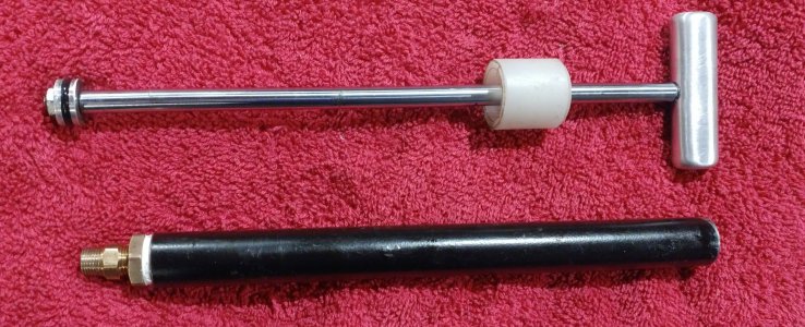
The cylinder and piston assemblies
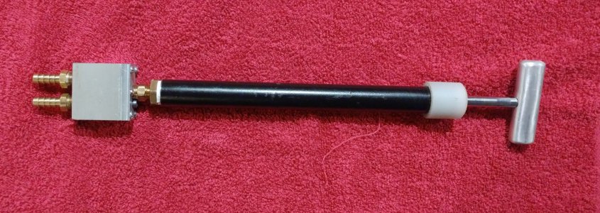
The assembled pump
Commercial lube pumps are available for this process for about $15 and over the years, I have owned several. They are made of plastic and typically only last a year or two before the plastic swells and the pump becomes unusable. I spent an afternoon on the internet looking for a more permanent solution to no avail so I decided to make my own. All materials came from my parts and scrap collection.
For the pump body, I chose an old air spring from some long gone vehicle. The spring was 8" long and had an internal bore of 5/8" which would give me about one ounce of lube per stroke. After making a small cut to relieve the gas pressure, I cut the ends off the cylinder and pulled the piston assembly out. Next, I cut the piston and coupling off the ends of the piston rod, leaving me with a 5/16" shaft. The shaft was turned to .191" on one end and threaded for a 1/2" with 10-32 by 5/16" long thread. The other end was threaded with a 5/16-18 by 1/2" thread.
A new piston was turned to .625" diameter from some 3/4" aluminum bar and a a groove cut to accept a 5/8" o.d. by 3/32" wide Buna-N O ring. Usually, I would make a detailed drawing of the part but in this case, I just winged it, turning until it looked and felt right. A .450 diameter groove gave the good fit for a tight seal without undo friction.
Next, threaded one end of the cylinder for 1/4 NPT. I left the other end plain as I didn't want to damage the O ring when I inserted the piston. I turned an end cap for an light press fit on the cylinder from a piece of Nylon bar. A 1/4 NPT x 1/8" NPT brass bushing was fitted to the cylinder.
The next step was to make the valve assembly for the pump. I decided to use two 5/16" ball bearings for the valves. For the valve springs, I selected one from my spring collection. From its shape, it appear to be from a compression spring for an electric motor brush. It had a 1/4" i.d. and .014" wire. I determined that the spring force was around 2 oz. for what would be a typical compression in the valve.
The valve body was made from a piece of 3/4" aluminum plate from the scrap box. The valve body was designed with the inlet and outlet both on one end and a piece of 1/4" plate containing the coupling to the cylinder on the other. The cylinder end was machined first with .156" through holes for the fluid passage drilled first. This was followed by boring one hole to .625" depth and milling a connecting pocket .125" deep with an 11/32" end mill. A 19/64" ball end mill, taken to a depth of .700" was used to cut the valve seat. The final seat was later formed by pressing the 5/16" bearing into the seat. Six holes for mounting the cover plate were drilled and tapped for 4-40 threads.
The valve body was flipped and two 11/32" holes were bored, one to .625" depth for the second valve seat and the second to .458" depth on preparation for tapping the 1/8" NPT hole. The valve hole was cut to .700" depth with the 19/64" ball end mill. The two holes were then tapped for 1/8" NPT. This completed the machining of the valve body. As a final step, a 5/16" ball was then firmly pressed in to form the valve seats.
The 1/4" cover plate was cut to size and the six .110" through holes for the mounting screw were drilled. An 11/32" hole for the 1/8" NPT plug was cut with the previously used end mill and tapped. A hole concentric to the valve hole was drilled, tapped and countersunk for 10-32 UNF for the purpose of a restraining pin for the valve spring completing the machining of the cover plate.
In retrospect. it would have been easier to move the 1/8" NPT hole in the cover plate to one side about .1" to provide more room for the restraining pin. Also, increasing the slot width and depth in the valve body would have simplified construction. One of the pitfalls arising from not doing complete modeling of the assembly.
The restraining pin was made from a flat head screw. The threads were removed from all but 1/4" using the lathe. Two nuts were used to provide for mounting the screw in the lathe. Nuts seldom have threads concentric with the hex feature. I could have made a custom bushing for this purpose but it was more expedient to just use a file to remove the threads. Again a non critical part; the threads were removed to prevent the spring from hanging up.
Two 1/8" MPT x 1/4 hose barbs were used for the connections to the outside world. One was counterbored to provide a seat for a valve spring.
The final bit of machining was to make a handle for the pump rod. A piece of scrap aluminum was used to make the handle, no particular size in mind, just what looked good. All six sides were milled to clean them up and a through hole frilled and tapped for 10-32 UNF. I could have written a program to cut the curves on the CNC mill but that seemed like a lot of work for a non critical part. I used a shoeing rasp to rough out the profile followed by progressively finer files, a piece of cloth backed sanding belt and finished with some 130 grit emery cloth.
Next was assembly of all the parts. The 1/4" NPT bushing was installed in cylinder, followed by a brass 1/8" NPT short nipple. One end of the nipple had to be shortened to not be proud of the end of the cover plate (see lessons learned three paragraphs up). The restraining pin was fitted in the cover plate. A 5/16" ball followed by the spring were inserted in the valve housing and the cover plate was fastened with six 4-40 screws. A 5/16" ball and spring were inserted in outlet valve, followed by the counterbored hose barb and the second hose barb inserted in the other hole.
The piston was place on the piston rod and secured with a 10-32 nut. The O ring was coated with oil and the assembly slid into the cylinder bore. The end cap was pressed in place and the handle screwed on the piston rod, completing the assembly.
I had tested the valve design using air and found the balls would unseat with less than 2 psi so I felt fairly confident in my design. For a test, I hooked some pvc tubing and tried pumping some way oil. The inlet valve worked fine, drawing the way oil into the pump but on the discharge stroke, the pump locked up. I was puzzled by this behavior as all the fittings and tubing were clear. Closer investigation show that the outlet valve would permit a small amount of oil to flow before locking up, about 1/2" of stroke. If I paused for a few seconds, could repeat the cycle. The light bulb came on; the ball was being push into seating on the bottom of the hose barb. I removed the barb and cut two cross slots in the threaded end which solved the problem.
I used the fill nozzle from the old commercial pump as it threads into the fill port and has a swivel joint. to facilitate installing and removal. I added a brass fitting to the intake hose t help keep it below the surface of the lube.
I changed the gear lube today and the pump did the job. It took about twenty seconds to fill the pump body due to the viscosity of the gear lube and the comparatively lower pressure difference (maximum 15 psi). The discharge stoke develops considerably higher pressure and so took less than two seconds. The whole refill process took less than five minutes with no mess. All in all, a great success.

Cut away of the valve body

Detailed drawing of the valve body.

The components of the valve assembly

Another view of the valve body

The cylinder and piston assemblies

The assembled pump

 Maybe this winter I will make one too. Thanks for the detailed drawings and write up.