Project advice needed

Jim F

H-M Supporter - Gold Member
H-M Supporter Gold Member
Joined
Sep 24, 2020
Messages
2,021
I am going to make a 3C collet holder and draw bar for my lathe.
It is a SB 9C.
Spindle bore is .765.
Any advice on what size black pipe to make the draw bar from and is tail stock offset the best way to cut the 3MT ?
What is a good length overall and total OD ?
Bottom left in attachment.
 

Attachments

  • Collet Adapters.PDF
    386.3 KB · Views: 37
Thanks for the posting.
I have the same lathe, part restored, so you can guess I am interested.
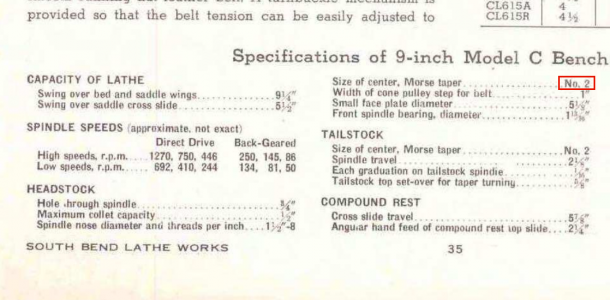
The catalog 5205 for SB9s says..
Hole through spindle ..... 3/4"
Maximum collet capacity 1/2"
Size of center, Morse Taper ....No. 2 [Huh?]

SB9C-Spec-fragment.png

Now that does confuse me!
Is it that you want to bore a MT3 Morse taper up the spindle, where there is already a MT2?
Be assured I am feeling pretty ignorant right now, but on this site, that's OK. They will help

I am going to have to double sure check what is up there. I have so far only used a chuck, and never thought to have collets, and I have near zero experience with them. That situation is about to change! I just need to get clear in my mind what you are about to do.

As to draw-bar - we can figure this out. Also, I am pretty sure there are HM expert members who can tell us.
 
Last edited:
Does your compound have enough travel to cut the morse taper? If so, that is another option. As for size, I would buy 3/4 inch od x .095 inch wall thickness tubing. This will you enough meat to cut the minor diameter for the .640-26 thread, and have a hole big enough to clear 1/2 inch stock.
 
A spindle is really hard stuff!
With tungsten carbide bits, I suppose that's OK.
 
My experience with South Bend spindles on smaller lathes is that they are all too soft and prone to excessive wear, noting that the bronze shell bearings were nearly unworn and the spindle worn excessivly.
 
My experience with South Bend spindles on smaller lathes is that they are all too soft and prone to excessive wear, noting that the bronze shell bearings were nearly unworn and the spindle worn excessively.
Oh dear! Maybe it is just the outside that got hardened?
I got my notion about "hardened" from the South Bend propaganda on page 1 of the Catalog 9 - HE.
It says "The headstock spindle is made of alloy steel with hardened and superfinished journal bearing surfaces".
Yeah - OK then. Strictly interpreted, the wording does say only the bearing surfaces were "hardened", grouped with being "superfinished"!

I know that using the cast semi-steel with graphite content direct onto hard alloy steel with an oil film between was a very robust, successful, and, importantly for the time, suitably low cost arrangement.

When dissimilar metals, one being very soft, are run in a journal, commonly it is the harder surface that wears, just like a car crankshaft on white metal. I had thought that if a South Bend spindle was always properly set with the right thickness oil film, wear was very low, and could take decades to become significant. So maybe I am wrong in thinking that, but I have not put my machine(s) through enough hard work to tell.

Does anyone ever go for making up a hardened replacement spindle?
Such a notion is, of course, another option for Jim. Make the whole spindle to suit yourself, keeping the one you have in case you mess up. There is also the poetic justice in having a machine make replacement parts for itself!
 

Attachments

  • South_Bend_9_1950_Catalog.pdf
    1.4 MB · Views: 4
My experience with soft South Bend spindles was with old machines, I expect newer ones have hard spindles, especially the ones with cast iron bearing journals. In the case of the two that I had experience with, the spindles were quite worn and the bronze bearings were in good condition, with the first one, made in the late 1920s, I had the spindle hard chrome plated and reground back to standard size; the second one was perhaps about the same age, but not having access to hard chrome, I simply just made a whole new spindle for it. I have neither of these machines now, but found a near perfect 9"Monarch Jr. lathe to take their place.
I'd guess that most of the later spindles were hardened where "the rubber meets the road", that is on the bearing journals, probably not the whole spindle. The advert. above seems to say that the spindle bearing surfaces are hardened and superfinished, implying that the whole spindle may be heat treated, but only the journals themselves are significantly hard.
 
Thanks for the posting.
I have the same lathe, part restored, so you can guess I am interested.
The catalog 5205 for SB9s says..
Hole through spindle ..... 3/4"
Maximum collet capacity 1/2"
Size of center, Morse Taper ....No. 2 [Huh?]

View attachment 340369

Now that does confuse me!
Is it that you want to bore a MT3 Morse taper up the spindle, where there is already a MT2?
Be assured I am feeling pretty ignorant right now, but on this site, that's OK. They will help

I am going to have to double sure check what is up there. I have so far only used a chuck, and never thought to have collets, and I have near zero experience with them. That situation is about to change! I just need to get clear in my mind what you are about to do.

As to draw-bar - we can figure this out. Also, I am pretty sure there are HM expert members who can tell us.
My lathe has a 3/4 capacity through the spindle and a MT3 taper.
Mine was born in 1947.
 
Last edited:
My lathe has a 3/4 capacity through the spindle and a MT3 taper.
Mine was born in 1947.
OK - thanks for that. I have a test bar with MT2 on one end, and MT3 on the other. I will be checking them out tomorrow.

Two lathes, one 9A is I believe 1947, or nearby, and the other is unknown. That one is a South Bend 9C with no serial marking in the place you would expect. I am told that South Bend lathes used by South Bend, and not sold, were like that. They were all eventually sold as used when SB ceased that production, and I think mine is one of those.

So in making a 3C collet holder, the Morse MT3 is to be on the collet holder, so it will mount up the SB9 spindle. Would that be the part at the bottom left of the drawing?

I think starts out between centers, with something reference MT3 put in there, and then adjust the compound angle while an indicator touches to it, until it tracks true. Then put your steel in between the centers to cut the paper. I haven't thought it all through yet, but once the rest of the outer has been made, you abandon the centers, and stick it into the spindle MT3 directly, and then drill and bore it.
 
Does your compound have enough travel to cut the morse taper? If so, that is another option. As for size, I would buy 3/4 inch od x .095 inch wall thickness tubing. This will you enough meat to cut the minor diameter for the .640-26 thread, and have a hole big enough to clear 1/2 inch stock.
I have 2 3/8" travel on my compound, so that should be enough.
The taper will be just over 1 1/2 "
 
Back
Top