Precision Matthews PM-728VT CNC conversion

I'm trying to tighten my Z-axis gib to reduce backlash and have a couple of questions.

Using a dial test indicator I was able to test that the ballscrew itself has almost 0 backlash. By the time the spindle head starts to move upwards though there is 0.07mm (~0.003") backlash. I've tried tightening the gib but seem to have 'bottomed out.' Actually the gib is so far out in one direction that the screw that holds it in place is starting to bend away from it.

So the questions: Does the direction of the gib taper matter? Mine tightens as it is moved upwards.
Anyone else run into this issue? What was the solution? Can I order a slightly thicker gib from P-M?
OK -- I guess I'll answer some of my questions.
The direction of the gib taper does matter. I was wrong about the direction for the Z-axis. The gib is thicker at the top and thinner at the bottom. So it tightens as the gib is moved (pushed) downwards.
P-M can provide a gib which is slightly oversized but you'll have to machine it down to size.

Even after quite a bit of trial and error, I could reduce the backlash to around 0.06mm (between 2 and 3 thousands of an inch). At some point, tightening the gib even more made it worse. I am convinced that due to the cantilever design of the z-axis lift mechanism this much play is inherent. To reiterate, there is no backlash at all at the bottom of the ballscrew itself which I tested with a dial test indicator inserted into the Z-column slot. But by the time the spindle head starts to move in the other direction there is 0.06mm of backlash. I think (hope) that the software backlash compensation will be able to take care of this.
 
Hi @sakumar

I have spent a lot of time with my gibs on the PM940M. I am not complaining, but here are some of my thoughts for you.

Yes, pushing in on the larger end provides tightening. The screw on the small end is for clamping it in place after moving the gib. However, if you leave it loose, or remove the gib screws and run the saddle along the ways then the gib will slide back and forth and can even get very tight. So after adjusting the gib with the screws always tighten the screws on both ends to hold the gib in place. Sure enough if you do not clamp the gib then the backlash can be different in the two directions!

You do not want the clamping screw to pinch the end of the gib into the ways. This is especially a hazard at the small gib end. If so this is applying lots of pressure at this one point, not a gib function at all as all .... the drag/friction is at only one end/point along the gib!

Yes, I found that if you adjust the gib too tight then the backlash can increases .. and it can increase significantly. If you tighten it too much it is equivalent to applying a lock. This backlash is a function of the load being driven by the motor etc. The drive load (motor coupling, bearings, lead screw itself, ball nut, gib, etc) tends to cause the lead screw to act like a spring being wound rather than resulting in motion of the saddle... when this drive load is heavier the backlash increases. I found that my ways, Y-axis, are not parallel, resulting in the gib being tighter at the wide area... and so the backlash increases at the wide position along the ways simply because the gib is too tight (increased load). I am still studying this in my spare time and trying to fix it by working on the ways...., so far I have made a huge improvement. Unless you rework the ways, you pretty much have to live with the backlash at the worst position or loosen things up so much that the saddle does not remain square. When I tightened up my gib where the ways are the closest together... then I found that the backlash, where the ways were wider, went from 0.00x to 0.0xx. Wow! You could even feel the springing of the y-axis crank handle.

I actually found that measuring backlash is the most effective method I have for adjusting the gib.

It is easy to compensate for backlash when cutting straight cuts. The software will not be able to do so on a curve, so I think circles always become ellipses. However, how often are you machining a circle in the plane of the z axis! When I am drilling an array of holes you can easily compensate for backlash by always approaching the next hole from the same directions. This is simple if you are writing your own g-code.

The gear driven head on my 940 is very heavy. I estimated it to be between 250 and 275#s +-. Nod is a something you live with and I think this weight actually bows the distance between the ways (pinches the ways toward each other) in the center position. I am not saying that the column bends over, it is just being collapsed together due to the weighted cantilevered head ... a very small amount showing up as way spacing decrease of a few thousands. This means that the head nods and the gib becomes looser in some positions. So backlash varies with vertical position. The solution to this is to reduce the head weight .. or some how make the column even stronger. Maybe a counter balance of some type. I think the head on the PM728 is significantly lighter and the machine is suppose to be much better made all the way around... so hopefully this is not much of an issue for you.

So, you might want to try to set the gib when you are at the top of the column by monitoring the backlash (setting it to be small) at this position... and then measure it at the bottom to see if it is still small. Of course the nod at the bottom position may increase.

Another thought, check the lead screw alignment. Assuming that the lead screw only has bearings at the motor end (top) then the bottom is free to flex when the ball nut is at that location, but it for some reason the ball nut is not properly aligned at the upper position and the lead screw cannot flex then this tightness can cause a load ... backlash.

Good luck.

Dave L.
 
Hi Dave L.
Thank you for the detailed response.
As you note, the Z-axis backlash is of less importance than the X and Y. I am getting about 0.02mm (less than 1/1000") backlash on X and Y.

I have decided to more or less live with the Z backlash of 0.07mm and rely on software compensation.

One problem compared to manual operation is that it is hard to get a feel for how tight the ways are and the mongo Clearpath servo motor has a lot of torque. One time I locked the z-axis, then forgot I had done so and jogged it up and found that the motor could still drag everything up! It made a different sound alerting me that there was a problem.

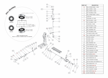
I have also added a jam nut to the locking nut on top of the z-ballscrew. That part is working perfectly. I inserted a DTI inside the Z-column just below the ball nut and it has no backlash at all! So all the backlash is due to the play and flex in part #14 in the diagram below. I have installed a Priest Tool power drawbar thus making the head heavier so that is also contributing to the problem.

Sanjaya
 

Attachments

  • Screenshot 2023-01-06 at 6.30.55 PM.png
    Screenshot 2023-01-06 at 6.30.55 PM.png
    1.3 MB · Views: 119
Thank you for the detailed response.
As you note, the Z-axis backlash is of less importance than the X and Y. I am getting about 0.02mm (less than 1/1000") backlash on X and Y.

I have decided to more or less live with the Z backlash of 0.07mm and rely on software compensation.

One problem compared to manual operation is that it is hard to get a feel for how tight the ways are and the mongo Clearpath servo motor has a lot of torque. One time I locked the z-axis, then forgot I had done so and jogged it up and found that the motor could still drag everything up! It made a different sound alerting me that there was a problem.

I have also added a jam nut to the locking nut on top of the z-ballscrew. That part is working perfectly. I inserted a DTI inside the Z-column just below the ball nut and it has no backlash at all! So all the backlash is due to the play and flex in part #14 in the diagram below. I have installed a Priest Tool power drawbar thus making the head heavier so that is also contributing to the problem.

Sanjaya
Did you check the preload on the double ballnut? I went down this same road chasing gib tightness and bearing preload for hours but it was just masking the real problem. Once I fixed my ballnut I went from 0.0045 to 0.0015 backlash if I remember correctly.
 
Did you check the preload on the double ballnut? I went down this same road chasing gib tightness and bearing preload for hours but it was just masking the real problem. Once I fixed my ballnut I went from 0.0045 to 0.0015 backlash if I remember correctly.
No I didn't -- can you provide a link on how to check the preload and also how I can fix it if I find it is out of spec?

But to reiterate -- I am pretty sure I'm getting almost zero backlash at the bottom of the ballnut as measured by a DTI inserted into the slot in the Z column.
 
Mine was obvious, If you can get a feeler gauge between the spacers its not preloaded. Others had the same problems with the pm ballscrews. if you do a quick search you will find the threads. Below is a video on how loose mine was. I talked to Matt and he relayed it back to the factory so hopefully the issue was resolved a long time ago but it never hurts to check. I can tell you that the cast iron part is not flexing... I am actually running one I made from 6061 with extra weight on the head and have no issue. My guesses are the M8 bolt moving(the boss is not a precision fit, ballnut preload, angular bearing preload/or quality, gib too tight.

 
Hi @sakumar

Good morning. If I could get my backlash down to your 0.02mm = 0.0008" I would be really happy!!! My current backlash on my y-axis is more like 0.003 to 0.004" and I am still working on it via losts of measurements and then modifying the ways. It used to be a lot worst. x and z axis are just as bad, but I have not begun to work on them. When I make my gib completely loose the best I get is about 0.002-0.0025" so when I get to that point I may work on other parts. Obviously I do not want the gib completely loose or the table/saddle will tilt, rock, rotate .. swivel.

Yes, it is amazing how much weight the CNC motors can move. My 940 has steppers and it can drag the Z-head up even when the locks are on. This is how I first discovered there was a problem with my gib clamp. The stepper would lower the head and not miss any steps, but when it lifted the head it would sometimes miss steps. This could be quite sever and was not due to the locks! Anyway, I stopped using the locks after I took my z-axis out (much later on) and found that the two lock screws were leaving big gouges in the back side of the gib. I wondered if these could be warping the gib. However, even this was useful information. I could see that the gouge marks had been moving around, indicating that my gib position was not stable. I also realized that gib was cut improperly and was being pinched against the dove tail at the small end rather than just being held in place. So it was acting like a clamp. I am guessing that because of this pinching, the factory also cut the gib off too short. I fixed this, but first you have to discover it.

You have double thrust bearings and a ballnut that can be adjusted. I wish I did. I agree with @GB21 take a look at this.

One problem compared to manual operation is that it is hard to get a feel for how tight the ways are and the mongo Clearpath servo motor has a lot of torque. One time I locked the z-axis, then forgot I had done so and jogged it up and found that the motor could still drag everything up! It made a different sound alerting me that there was a problem.

Using backlash to set your gibs (with a CNC system):

So you have clear path servo motors rather than steppers. However, I think they still function more or less like steppers... I think they take in a step signal from the controller and then the motor's internal electronics moves the shaft until the step is reached. So the shaft turns and if the saddle does not move it is probably because of some slack (or spring being wound) in the rest of the chain of components between the motor and the saddle. Anyway, I think you can use my approach toward measuring backlash to set your gib position. Gib too tight and the backlash increases. Too loose and the backlash is determined by some machine part other than the gib setting. The procedure is the same as any backlash measurement but I use the CNC pendant to move 0.001" steps. Place the micrometer probe between the spindle and a block on the table. Traverse in one direction a sufficient amount to over come any backlash. Record the micrometer reading or zero it. In the reverse the travel direction supply a signal to the motor to tell the motor to move say ~ 0.010" as determined by the pendant (not the micrometer). I do this in 0.001" steps and watch the micrometer dial. Now measure the actual motion as determined by the micrometer. The difference between the actual distanced moved vs. the requested move is the backlash. I found this technique to be very effective, especially if you move farther than it takes to just cause the micrometer to "start to move" ... as even the backlash value is non-linear. If you did not see any backlash then tighten the gib until you do. When the backlash starts to increase then back the gib tightness off a bit. You might want to note the gib screw depth. You should do this at several saddle positions along the way until you find the place where the backlash is the smallest. This will be the point where the two dovetails of the way are the closest together. Set the backlash here to just be governed by the gib tightness. Then measure the backlash at other saddle positions and see if the dovetails of the ways are parallel. (Note, the gib/way interface is not a perfect match. It maybe an awful match. In which case the gib may actually only be contacting at 2 points or a small region along the saddle length if it is truly unbending/stiff. These two points could be close together or far apart. If the ways are not perfect(?) then the contact points could actually be different depending upon the saddle travel position. If the gib is made with an incorrect tapper, to match the saddle dovetail tapper, then the gib will only contact near one end. If this is really bad you might be able to see it in via the saddle rotating about the gib contact point.)

I have not done it in detail, but I think you can actually calibrate the backlash measurement to determine the dovetail/way parallel error. You can determine the tapper of the gib and so when you screw in the gib screw you know how far it went in and so you know now much spacing you have used up between the dovetails with the gibs increased thickness. Since, I have not tried to work out these details I am not for sure how well this will work, especially since it is probably not a linear response. Nevertheless, since I am still working on the dovetail parallelism of my machine I my work at this. People usually measure the parallelism by fitting cylinder rod in the dovetails to make contact to the dovetails at two points... and then using a large micrometer to measure the distance between the outsides of cylinders. Do this at several points along the way travel and the difference is the parallelism error. I am currently building a micrometer to do this well... I hope. However this has its own limitations in that the surface that the saddle sits on is outside of the dovetails. If this surface is not flat then the cylinder measurement may not be valid/accurate as the cylinder only touches at two points. So I think the backlash measurement could actually be preferred.

By the way, if the gib is really too tight you can feel it as you had crank the lead screw. When it is way over tight or there is some other binding you will turn the handle and when it is released it will spring back ... a bit. Of course you have to power off the servo motors to do this. With stepper motors one might also observe the magnet cogging.

Still learning.

Dave L.
 
Mine was obvious, If you can get a feeler gauge between the spacers its not preloaded. Others had the same problems with the pm ballscrews. if you do a quick search you will find the threads. Below is a video on how loose mine was. I talked to Matt and he relayed it back to the factory so hopefully the issue was resolved a long time ago but it never hurts to check. I can tell you that the cast iron part is not flexing... I am actually running one I made from 6061 with extra weight on the head and have no issue. My guesses are the M8 bolt moving(the boss is not a precision fit, ballnut preload, angular bearing preload/or quality, gib too tight.

Thanks so much for the tips!

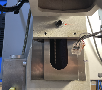
The M8 bolt was definitely a problem. See photo below (although the shift is exaggerated due to parallax) . At some point it had shifted to the left and as a result pulled the ballscrew to the left as well. I loosened it, adjusted the position and retightened it. Google shows that an M8 socket head screw should be tightened to 41 Newton-meters. My smaller Tekton torque wrench only goes up to 28 N-m, so I tightened it to at least that much.

After that I also noticed a distinct groaning noise when the head changed direction. That was because I had tightened the gib too much. Eventually I loosened it by a little more than two turns and the noise went away.

So now the backlash on the Z-axis is about 0.0018" (0.045 mm) and I'm very satisfied with that.
 

Attachments

  • Screenshot 2023-01-07 at 4.29.10 PM.png
    Screenshot 2023-01-07 at 4.29.10 PM.png
    3.2 MB · Views: 132
Update: I plan to make a video of my current setup to share but also to have a snapshot of where the development of the mill is at present.
Current projects:
1. Omron speed encoder attachment.
2. 4th Axis ( a big caveat is the backlash as noted by @macardoso in this post). not sure how I am going to solve it.

ROTARY ENCODER.
I posted about the Omron rotary encoder before (here and here in the 3D printing subforum). My current setup is geared, with one large gear on the spindle and an identical one with the encoder. Because of interference constraints from the Priest power draw bar, I need an intermediate wheel which rotates twice as fast -- so at RPMs above 1,000 the system is loud, and at 4,2000 RPM it is a screamer. Probably a sum effect of vibration in the support and the two wheel interfaces.

The system works and can be used for tapping, but am curious about a pulleys-and-belt system to replace the geared wheels in the hope of quieter operation.

IMG_1399.png

In the current setup this is the support. The element in the bottom right is the bottom plate that attaches to the spindle housing, replacing the Priest tools PDB support -- hence the 4 extra screws. The element at top left attaches the housing of the gears and allows adjustment. The pieces are connected via the two struts that are glued with CA glue.

IMG_1400.png


This is the assembled system.
 
Last edited:
Back
Top