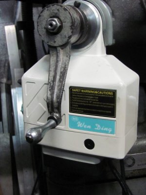
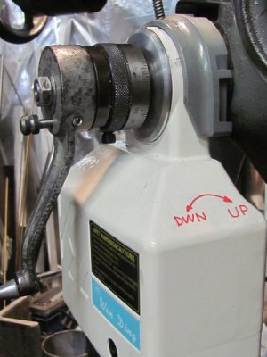
Been wanting power feed in X and mostly Z. Bought a pair of 150in/lb units designed for a Bridgeport ($254 ea, free ship). Proto work is done and tested. Final assembly is waiting on lead screw ball bearing and a couple don't drill that just yet holes. So, below is a list of make, modify and buy parts.
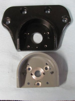
Modify: Bridgeport power drive mount - this mount supports the power drive unit and replaces the right side Rockwell X axis lead screw bearing holder. The mount is modified to use the 3 existing 1/4-20 Rockwell. The Rockwell hole pattern interferes with the mid power drive mount holes but there are two other mount holes that can be xfer punched for 6mm drill n tap.
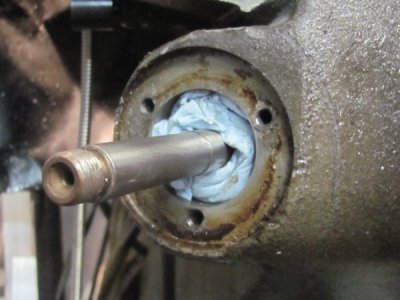
edit: Cut off threaded portion of provided worm gear. This leaves the threaded portion of the Rockwell lead screw exposed allowing the lead screw extension to attach.
Make:
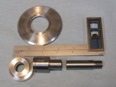
Lead screw bearing holder (15x35x11), supports lead screw bearing and attaches to modified bridgeport power drive mount.
Power Drive sleeve - Mates power drive needle bearing and worm gear ID to Rockwell X axis lead screw OD. Requires 1/8" broach and customiaed woodruff key.
Rockwell X axis lead screw extension - Allows use of existing Rockwell dial & handle. Requires 1/8" keyway cut and woodruff key.
Bridgeport power drive worm gear chip shield - 3.125 x 0.22" aluminum disk, undercut to fit the power drive casting.
Buy:
15x35x11 seal bearing
3ea 1/4-20 CS
2ea 1/4-20 x 3/16 set screws
Will post pics of parts before/after. If there is interest, will work on dimension dwgs.
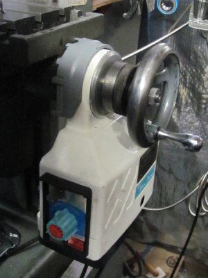


Last edited:

 .
.