- Joined
- Dec 18, 2019
- Messages
- 7,333
I bought the power feed when I purchased the mill, but just got around to starting the installation. Something about not having enough electrical outlets. Recently fixed the outlet issue by running a couple of 20A circuits. When I got the power feed, I briefly looked at the instructions that came with it, and couldn't understand it at all. The instructions seemed to have nothing to do with a PM25.
Yesterday, I went to the PM site and found a new (to me) document to download. It was a lot more understandable, and it became obvious what to do. I thought this would be a project of the day. Not quite. However, I managed to install this.
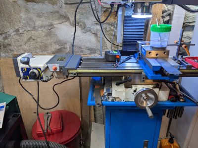
Surprisingly, the gear adjustment was pretty easy. Once I figured out the rheostat setting was too low, could get the table to traverse back and forth. Not too much gear noise.
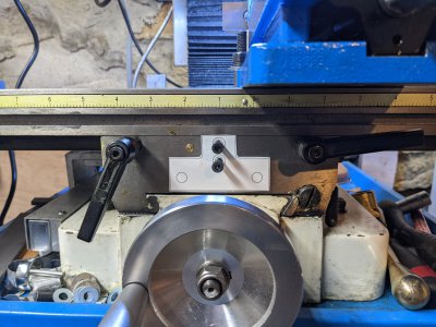
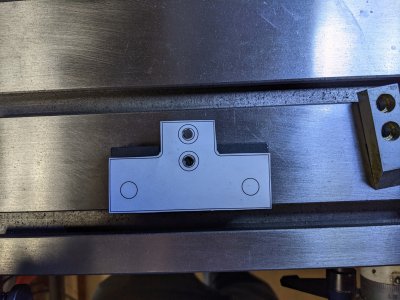
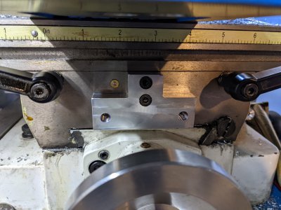
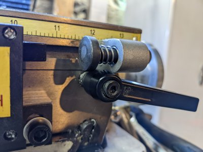
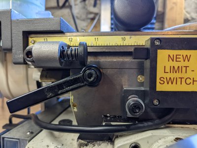
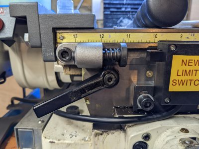
Unfortunately, the mounting bracket for the limit switches is incorrect. The bracket is rectangular, with 2 of the holes in the wrong place. The supplied bracket would block the oiler on the Y-axis. It isn't tall enough to pickup the two screws. It is just the wrong piece.
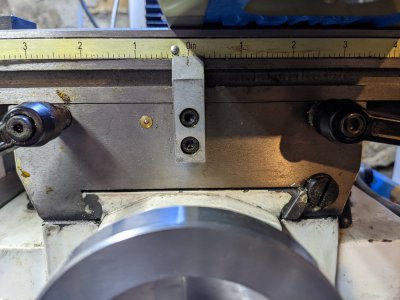
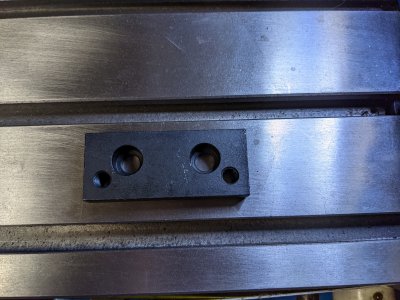
The two outer holes on the bracket are correct for the limit switch. The two inner holes do not match my machine. The bracket is not tall enough to have both vertical holes.
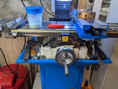
Of course I could make one. As you can clearly see, I do have a mill. It is disappointing that the wrong part was supplied. (But it is my bad, that I hadn't installed this in a year. Should have noticed this much earlier.) Does anyone have a sketch of what the bracket should look like? I'm guessing something like an inverted tee, but it would be nice to have the right spacing for the holes. If you have a sketch of the part, or a photo, it would be great. The photo in the PM download gives a hint, (what I received is incorrect) but not quite enough to design to.

Cable management seems to be left up to the user. Not sure what I am going to do just yet. The power feed isn't that professional looking in my opinion, but it does work. Bending cables as shown above, isn't a good thing to do. The limit switch cable will be subject to a bit of wear
Yesterday, I went to the PM site and found a new (to me) document to download. It was a lot more understandable, and it became obvious what to do. I thought this would be a project of the day. Not quite. However, I managed to install this.

Surprisingly, the gear adjustment was pretty easy. Once I figured out the rheostat setting was too low, could get the table to traverse back and forth. Not too much gear noise.
Unfortunately, the mounting bracket for the limit switches is incorrect. The bracket is rectangular, with 2 of the holes in the wrong place. The supplied bracket would block the oiler on the Y-axis. It isn't tall enough to pickup the two screws. It is just the wrong piece.


The two outer holes on the bracket are correct for the limit switch. The two inner holes do not match my machine. The bracket is not tall enough to have both vertical holes.
Of course I could make one. As you can clearly see, I do have a mill. It is disappointing that the wrong part was supplied. (But it is my bad, that I hadn't installed this in a year. Should have noticed this much earlier.) Does anyone have a sketch of what the bracket should look like? I'm guessing something like an inverted tee, but it would be nice to have the right spacing for the holes. If you have a sketch of the part, or a photo, it would be great. The photo in the PM download gives a hint, (what I received is incorrect) but not quite enough to design to.
Cable management seems to be left up to the user. Not sure what I am going to do just yet. The power feed isn't that professional looking in my opinion, but it does work. Bending cables as shown above, isn't a good thing to do. The limit switch cable will be subject to a bit of wear

