- Joined
- May 14, 2013
- Messages
- 104
In the spirit of this sub-forum "learn how to machine", I present my latest failure.
The goal was to create a vise clamp for the small 'toolmaker' vise (don't know the correct name) that came with my mill. It has a series of holes in the side (which, in retrospect, I assumed, were) for clamping. It did not, however, come with any clamps, so I've either not been using this, or clamping it very poorly.
Start to "finish" this took about 3 hours, although I had lots of fiddling on the lathe getting the new QCTP stuff set correctly.
What went well?
What didn't go well?
What will I do differently now?
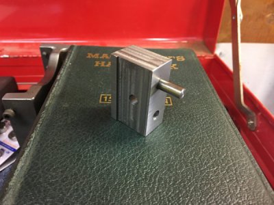
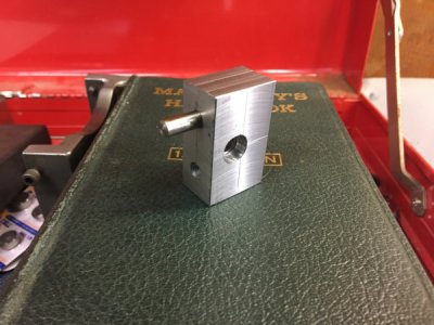
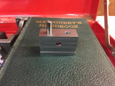
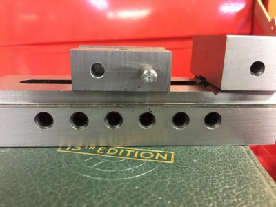
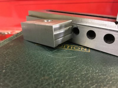
The goal was to create a vise clamp for the small 'toolmaker' vise (don't know the correct name) that came with my mill. It has a series of holes in the side (which, in retrospect, I assumed, were) for clamping. It did not, however, come with any clamps, so I've either not been using this, or clamping it very poorly.
Start to "finish" this took about 3 hours, although I had lots of fiddling on the lathe getting the new QCTP stuff set correctly.
What went well?
- Flycutting! I can now get pretty smooth uniform surfaces (Note: starting with irregular surfaces definitely make flycutting take longer and 'catch' more often - a definite reason to do very straight hacksaw cuts)
- Learned how to use a wiggler set for locating holes, yay garagePuter for YouTube instructions
- Press fitting recycled stainless rod in the vise, starting to get a feel for what a press fit is
- Taking the plunge away from slathering everything with motor oil - stuff still cuts! Less mess!
- My filing technique is improving, can get a more consistent edge when deburring (I suppose I should get a deburring tool)
What didn't go well?
- Flycutting is very tedious on a mini-mill with no power feed
- I am apparently really bad (or, perhaps more kindly, very inexperienced) at measuring and laying things out
- The hole spacing was off by half a diameter (but pretty much exactly half! so that's a win for layout)
- The hole height was just arbitrarily scribed to the middle of the face (hole height was actually crucial, lol)
- This was, honestly, probably me rushing plus inexperience. Pretty dumb mistake.
- Drilling one of the holes didn't work out, very loose fit
- Probably because the drill bit got stuck - need to ensure drill chuck is super tight
- Need to understand proper speeds/feeds for drilling
- I don't have any way of milling a 10mm blind hole w. square shoulders
- Using my new parting tool on the lathe was a spectacular failure (most likely a speeds/feeds + tool height thing)
What will I do differently now?
- Having drawings figured out ahead of time (and checked/verified!) is crucial - measuring on the fly is probably a bit advanced for me
- The square design looks kinda silly, need to investigate ways of cutting large chamfers (get angled parallels?)
- Really gotta get an x-axis power feed going
- X&Y table locks for drilling...is that what the little socket head bolts are for?? (one of them was stripped)
- A DRO would seriously make things go faster for layout/accurately milling pockets
- Boring head for expanding 3/8 holes? Or just bigger end mills? (or both!)


