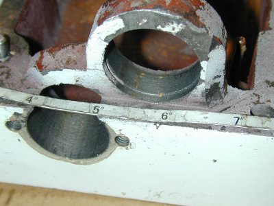
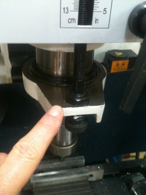
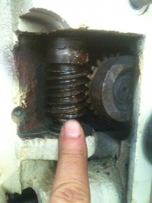
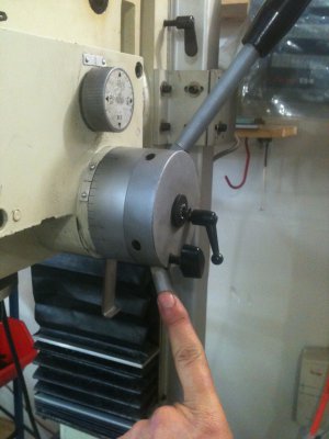
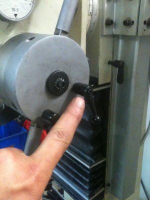
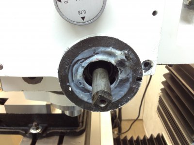
After reading Ratz' post about all of the junk he found in his PDF gearbox, I decided to bite the bullet and take mine off to see how it looked. Unlike Ratz, I am not an experienced machinist so I was somewhat reluctant to take apart something that was working but Ray encouraged me to give it a try, so I did. Removing the gearbox could hardly be simpler. I first moved the table all the way to the left to limit the exposure if I were to drop something. I also put a thick dense rubber pad on the remaining part of the table as added protection. Next I removed the SHCS (Socket Head Cap Screw) and washer that is in the center of the quill lever assembly directly between the two quill levers. With a little back and forth, the whole thing came right off. The first photo below shows what I found underneath. There was a little grit but, overall, not too bad.
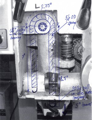
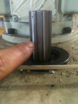
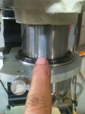
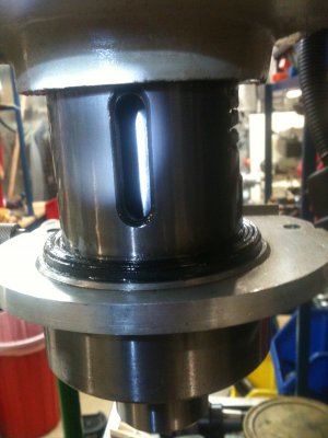
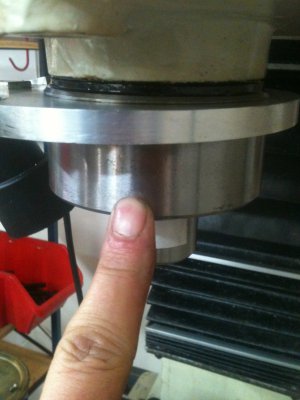
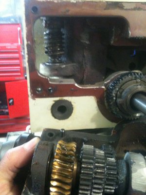
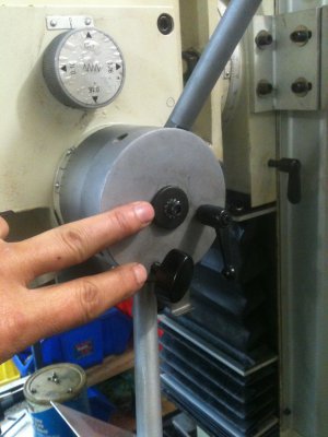
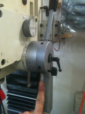
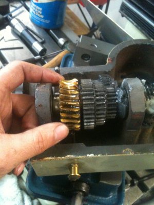
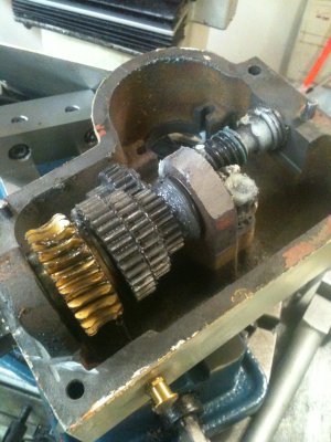
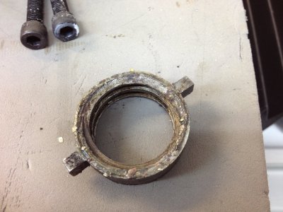
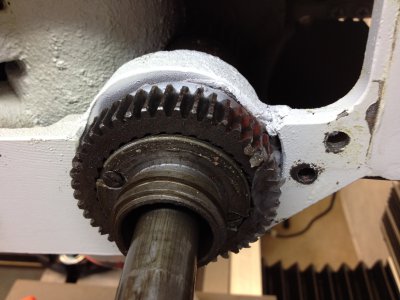
Next, I loosened the 6mm SHCS located at each corner of the gearbox. Once they were fairly lose but still engaged, I inserted a sharp flat bladed screwdriver (I know... that's not what a screwdriver is supposed to be used for) in the seam between the gearbox and the head and gave it several light taps until the parts separated. Then I tapped on all sides with a dead blow mallet as I gently pulled the gearbox away from the head. Once I was pretty sure the gearbox was free enough to remove I pulled out all four SHCS and removed the gearbox. Photos 2 through 4 show what I found. The ring in photo #2 had the worst contamination, but it wasn't grinding grit like I was expecting, instead it was more like Bondo dust or paint flakes. Anyway it cleaned up quickly. Photo #3 shows what that ring was (left-hand) threaded onto. Overall, not too bad, just minor contamination. I removed the two slot headed screws shown in #3 and pulled off the flange that the screws retain. Inside, there are two spring loaded pawls that engage the larger ring gear shown in the picture. It was pretty clean inside so I didn't remove the pawls. I just rinsed everything good with WD-40. Before I replaced the flange, though, I found that the ring gear did not revolve freely. I couldn't see a way to easily remove and I didn't want to bite off more than I could chew so I just kept turning it back and forth and spraying it with WD-40 until it was free. I didn't really find what was causing it to be stiff but it seemed to be getting better the more I fiddled with it so I just kept it up until it felt reasonably free. I then re-rinsed the pawls and coated them with a light coat of grease.
Next I cleaned up the gears. Again, they weren't too badly contaminated so I just rinsed liberally with WD-40 and scrubbed off the grease with an old toothbrush. I had noticed before I took the gear box off that whenever I turned quill feed wheel on the front of the mill, I could hear a crackling sound which I took to be grit in the gears. With the gearbox off, I was able to determine that the crackling sound was caused but air getting trapped in the grease on the gears and making a popping sound when the bubbles burst. I am not sure what kind of grease is used at the factory, but it seemed pretty stiff to me considering the low speed, low load usage these gears will see. Since I now know that it is easy to change if I ever need to I opted to use a lighter NLGI grade 0 grease. If you are interested, it is John Deere Special-Purpose Corn Head Gun Grease AN102562 which, as the name implies is designed for use in corn harvesters. Anyway, it's great stuff. It has extreme pressure and rust preventatives, it is good at all temperatures and it stays where you put it even though it is fairly soft. It is specifically designed for use on slow-speed gears.
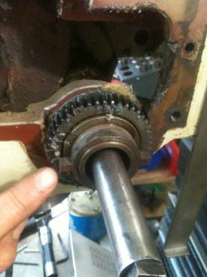
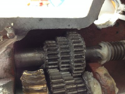
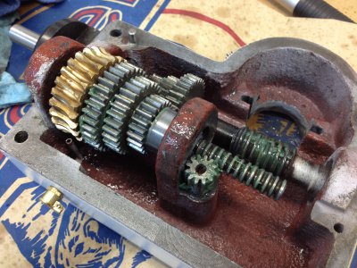
Once I got the old grease out and the new grease in, I found the entire gear train much easier to spin (Photo 5). By the way, if any of you were wondering where the oil that you put in the little oil cap on top of the gearbox goes, you can see it in the lower left of photo #5. Looks to me like it just drips oil on the brass gear. I did the same type of clean up to the quill lever assembly and then put everything back together. It is fairly easy to reassemble. The two tabs on the left-hand threaded ring in photo #2 must be lined up with the slots in the gear casing and the worm gear that drives everything must be properly engaged. Don't force anything! When it's all lined up it will just slid into place. In Photo #3 there are two holes to the right of the ring gear I talked about earlier. One hole is threaded and the other is not. The non-threaded hole receives a dowel pin in the gearbox and there is another one just like it on the left-hand side. These pins really help to line thing up but mine were loose so I had to make sure to push them into position.
The first time I re-mounted the gearbox, everything seemed great until I engaged the power feed. The power feed didn't work and there was a rhythmic clicking sound coming from inside. I thought I had screwed up big time and expected to find powdered gears when I opened things back up. Luckily there was no damage. As far as I can determine, the drive pinion from the head has a clutch mechanism on it that maybe protects the gear train if its load capacity is exceeding some limit. The worm gear on the drive pinion has a castellated top that mates to similar castellated part coming down from the top. There is a spring below the worm gear that pushes it up and keeps the castellated parts mated. The angles of the mating castellated parts are such that they exert some downward pressure on the worm gear as the torsional load increases. I think that if load gets heavy enough, the castellated parts will cam out and slip rather than forcing the gear train to take an excessive load. I believe the clicking I was hearing was the two castellated parts sliding by each other. I don't know what caused the issue. I looked everything over and remounted the gearbox to the head just as I had before but this time, luckily, it worked.
That's pretty much it. I think that my particular machine would have worked for years as it was but it is quieter and it has a much better feel to it now and I have peace of mind knowing that my gearbox isn't doubling as a grinder. Thanks to Ratz for giving me the idea and to Ray for encouraging me to go for it. I am glad I did. I now know much more about my mill and am more confident and less fearful of screwing it up.
I apologize for the organization of this post. I wanted to display the photos with text in between but couldn't figure out how to do it. This is my first post with pictures so obviously, I have a lot to learn. As I said I am a neophyte when it come to machining and my primary purpose of being in this forum it to learn and give back a little when I think my limited experience might be useful to someone else. I hope you will all feel free to shoot this full of holes and tell me what I might have done differently or better. I will continue to makes the same mistakes unless someone points out my errors. Thanks to all of you who have posted! I have learned a lot!!


