Pivot Locator/Radius Setting Tool for U3, D Bit Grinder

Joe-R

Registered
Registered
Joined
Mar 15, 2021
Messages
50
Hello fellow U2/U3 D Bit (Universal) cutter grinder users,

I have a Shars U3, D Bit Grinder and I got tired of trying to locate my lathe and D bit cutters over the pivot point of the work head by roughly guessing where the pivot point actually is (the need for locating the pivot point is mostly just for grinding various radii in tooling). It seems they should have included some sort of pivot point indicator in the original design in my humble opinion but it is what it is :)
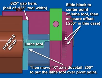
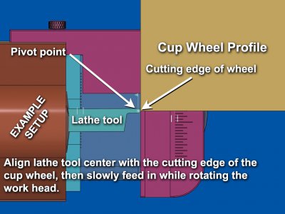
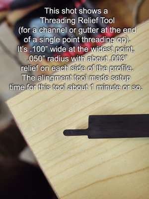
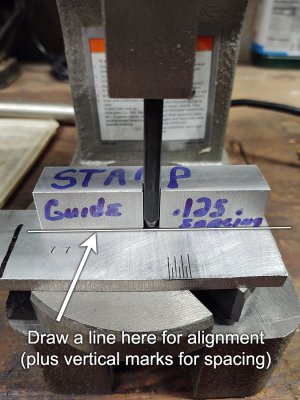
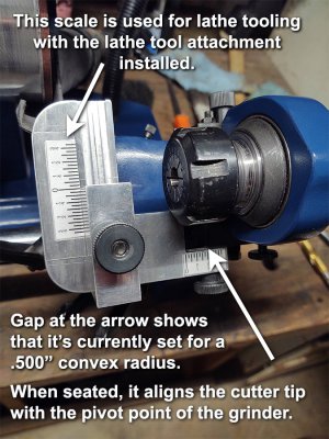
I make a fair amount of form tooling for the lathe and D bits for the mill so I decided to make a custom fixture that helps with locating the pivot point for setting offsets for various concave and convex radii.
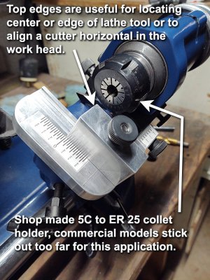
I also wanted something to help with setting a cutter horizontal to the work head without having to guess, the included arm below the work head is too short to reach the end of the cutter in some cases but that depends on the amount of stick out.

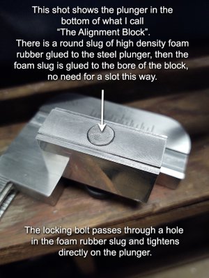
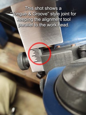
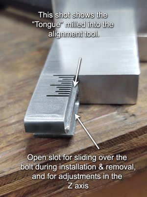
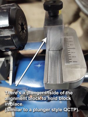
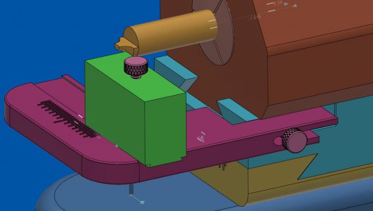
This locator/radius setting tool easily slides on or off by loosening or tightening the newly added thumb wheel on the side of the Z/X dovetail base, the side of the locating tool has a slot in it for that purpose (see attached fusion model snippet).
It literally takes no more than 2 or 3 seconds to install or remove it.

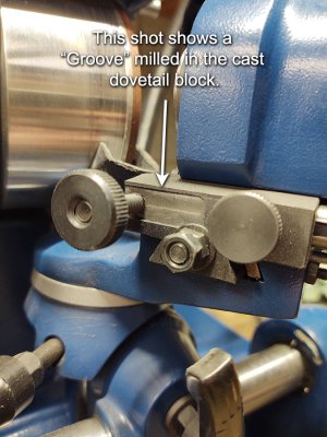
I hope a lot of the design is self explanatory in the marked photos.

However, if there is any interest in this setup, I can go farther into how I use it and share a few more photos if needed.
I can also share the CAD files or the drawing if there is any interest.

Just thought I'd share an idea that works well for me.

All the best,

Joe

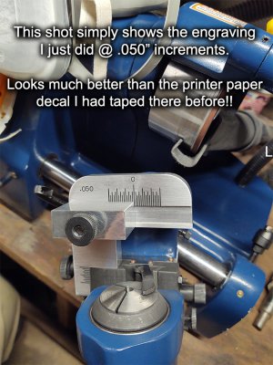
P.S. For those who have noticed that the scale marks and number are not engraved, I just didn't have time to engrave them when I made this tool.
And since it's not for a paying customer, it may remain that way? :)
I modeled the graduations in Fusion so I could print them with a paper printer at 1:1 and just tape them on for the time being.
I used fractions on the scale because the scales on the work head are marked in fractions, I decided to keep it consistent.
 

Attachments

  • Pivot Locator and Radius Gauge 3T.jpg
    Pivot Locator and Radius Gauge 3T.jpg
    479 KB · Views: 360
  • Pivot Locator and Radius Gauge 4T.jpg
    Pivot Locator and Radius Gauge 4T.jpg
    547 KB · Views: 366
  • Snippet of Fusion Model.JPG
    Snippet of Fusion Model.JPG
    62.9 KB · Views: 341
  • Pivot Locator and Radius Gauge 1T.jpg
    Pivot Locator and Radius Gauge 1T.jpg
    540.3 KB · Views: 364
Last edited:
That's a neat little tool! There are two relationships that you need to set, one is the work to the center as addressed by this gauge, the other is the center to the grinding wheel. I see you made yourself a cross mark on the pivot point. I did the same, except I took that part out of the machine and chucked the axis up in my lathe, allowing me to drill an exact center point in the casting. Then I made a brass point and pressed it into the hole with a mallet. It's very useful, especially since the grinder throws sparks and dust on that spot, obscuring markings quickly. Your tool transcribes the pivot point very precisely, it's gotta be better than my version of eyeballing against a steel rule!
 
Hi John,

Yeah, I thought about machining a hole in the casting at the pivot point, then add some type of post or pointer to vertically extend the pivot point as you did but the idea of having some sort of scale for adjustments was very appealing to me. It was a half days’ worth of time and I'm semi-retired so what the heck :)

I forgot to mention in my original post that I frequently use 5C collets that have a square hole in them for grinding square lathe tooling, it saves time by not having to change the head out for the lathe tool attachment and it's easier to setup in general.

I have attached a couple of snippets from Fusion 360 showing an “Example Setup” for those who may be having a little trouble understanding how this new setup tool is used.
Oooops, I made a mistake in the top left corner of the first snippet, the "Gap here" should read .0625" instead of .625", that could be confusing for anyone to read correctly!
I'm not very good at explaining things!! :(

I tend to model most things in Fusion 360 so I can test how I plan to use the real thing before making the real thing or if it has a lot of parts with critical measurements, I often use slider, revolve and various other joints to help with virtual testing.
It’s far better than having to keep re-making the real thing :pickaxe:

I rarely model things that are easy to keep in my head but that’s not as easy as it used to be. :rolleyes:

Having too much fun with smileys!!

Thanks for the response John!!

Joe
 

Attachments

  • Snippet of .625 radius setup to grind a form tool for the lathe 1T.jpg
    Snippet of .625 radius setup to grind a form tool for the lathe 1T.jpg
    340.4 KB · Views: 287
  • Snippet of .625 radius setup to grind a form tool for the lathe 2T.jpg
    Snippet of .625 radius setup to grind a form tool for the lathe 2T.jpg
    281.6 KB · Views: 284
Last edited:
Nice job on the fusion drawings! That makes it very clear. I'm going to have to find some time to brew one for myself. Thanks for posting!
 
Nice job on the fusion drawings! That makes it very clear. I'm going to have to find some time to brew one for myself. Thanks for posting!

Hi again, John

Glad you like the setup!
I just wanted to share one of many machine mods that has made shop life a little easier for me and if it helps to make someone else's shop life a little easier as well, then I am happy :)
Sometimes half the fun of machining is making modifications like this for our own machines!

I admit that this post has inspired me to finally go ahead with engraving the graduation marks and numbers in the plate.
I think I will make the graduations every .050" though, it just makes more sense than every .0625"!
I should have thought of that in the beginning!

Have a great day John!! :)

Joe
 
Hi John (and whoever else that may be lurking and possibly thinking about making one of these devices),

I have uploaded a few more photos showing more details on the modification.
I can upload working drawings for anyone that has a grinder made the same as the Shars unit.

I can only imagine that some of the machines out there are made by the same company but with various brand names and colors?
I have no clue which are which and I'm sure there are way cheaper knockoffs than the Shars knockoff of the Deckel SO grinder!

Anyway, I did the line engraving but the stamp set I have for numbers is too large, I need to find a good set about half the size of what I have now (maybe 1/8" or 3mm?)
I use my arbor press and a shop made guide for aligning letters & numbers (just a block of aluminum with a .250x.250 notch in the side), I haven't thought seriously about buying a CNC router yet.

All the best!!

Joe
 

Attachments

  • Groove milled in side of casting.jpg
    Groove milled in side of casting.jpg
    529.1 KB · Views: 285
  • Plunger in the alingment block.jpg
    Plunger in the alingment block.jpg
    456.6 KB · Views: 260
  • Shows engraving and graduation increments.jpg
    Shows engraving and graduation increments.jpg
    516.6 KB · Views: 274
  • Tongue and groove and engraving .jpg
    Tongue and groove and engraving .jpg
    493.1 KB · Views: 267
  • Tongue and slot milled into alingment tool.jpg
    Tongue and slot milled into alingment tool.jpg
    431.7 KB · Views: 275
  • Thread relief tool.jpg
    Thread relief tool.jpg
    535.5 KB · Views: 276
Thank you for the extra detail pics, Joe! I am definitely going to replicate this when I get caught up. Hey, I'm curious, do you strike your stamps, or do you actually press them? I haven't made a stamp alignment block yet, and my hand strikes look like a child was at work on them. Pressing seems like a good idea, never heard that before. Might've just learned something new!
 
Thank you for the extra detail pics, Joe! I am definitely going to replicate this when I get caught up. Hey, I'm curious, do you strike your stamps, or do you actually press them? I haven't made a stamp alignment block yet, and my hand strikes look like a child was at work on them. Pressing seems like a good idea, never heard that before. Might've just learned something new!

You are very welcome!

Yeah, most of my past stamping projects looked pretty bad, I think a child could have much better than me!!

I find it much easier to use a guide block and work to a pencil line using the arbor press.
The arbor press is a more precise way of keeping everything lined up the way I want it and it practically eliminates misalignment and if needed I can re-seat the stamp in the impression left from the arbor press, then deepen the impression using the strike method but I use a small dead blow hammer with a brass head, the "Bounce" that comes from a solid hammer strike produces bad results every time (for me anyway).

Aluminum can usually be done in one go with the arbor press but some steels require a little more work.
I thought about using the hydraulic press for steel but I haven't tried that idea yet.

The guide couldn't be any simpler than what I use as shown in the photo and of course the hand marker writing on the stamp guide is a good indication that I get lazy from time to time when it comes to the small stuff meant only for me :)
Anything I do for other people always gets the full finished look.

All the best!

Joe
 

Attachments

  • Stamp Guide  - .250 Shank - .125 Spacing.jpg
    Stamp Guide - .250 Shank - .125 Spacing.jpg
    543.7 KB · Views: 284
This is a really cool idea! I'm still wrapping my mind around this. I am still contemplating how to calibrate it. That is, find the exact pivot point, in order to make the tool accurate.
The smaller scale, z axis, parallel to the length of the tool, I take it you set that in the center for no radius, closer to the wheel for convex radii and away from the wheel for concave.
I too want to make very accurate half round nose or quarter round nose lathe tools.
Thanks for sharing this.
 
I can upload working drawings for anyone that has a grinder made the same as the Shars unit.
Beautifully done project. I also have the Shars grinder and have struggled with locating center accurately.
I'd love to have the drawings. Thanks.
 
Back
Top