Phasing the Universal Joints on an Atlas Mill

JPMacG

Active User
H-M Supporter - Silver Member
Joined
Mar 22, 2014
Messages
870
The table of my Atlas MFC horizontal mill speeds up and slows down in synchronization with rotation of the drive shaft. I suspect the cause is that the two universal joints are not properly phased. Does anyone know how they should be oriented? Or can anyone provide a photo of the joints on an Atlas mill with a table that advances at a constant speed?
 
In the automotive and HD truck world the yolks all must be aligned with each other.
Also, even when properly aligned, as the angle increases, the speeding up and slowing down of the moving parts increases.
 
the first picture (poorly) shows the phasing.
the feed worked as intended on my unit without binding or change in speed.


i no longer have the lil beast, but she was fun to play with.


another thing to consider is wear in the sliding joint, as well as wear in the universal joint.
as the clearances become larger, the gaps between parts create a slowing, then speeding up effect.
this may be due to the lag in contact between the pin and block and then compounded by the clearance imparted in the 2 part telescoping shaft.
between these factors, we have high potential for head scratchin'
 
Conclusion was incorrect...
 
Last edited:
I could be wrong but isn’t it by definition constant velocity joint because it has two joints? I think the velocity occillates on single joints. My guess is the speed up and slow down is due to wear in the gear train and in the table feed.


Sent from my iPhone using Tapatalk
 
You're right. I was thinking about front axles. The angular velocity of the prop shaft oscillates but not the load unless the input and output shafts aren't parallel.

Try looking for something binding.
 
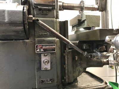
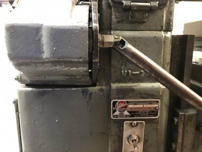
Here are photos. Compared to Ulma Doctor's setup mine is wrong. The variation in table speed is very cyclic. If I were to plot table speed versus time I believe it would look like a sine wave. I don't think the variation is caused by binding.
 

Attachments

  • IMG_3503.jpg
    IMG_3503.jpg
    744 KB · Views: 28
  • IMG_3504.jpg
    IMG_3504.jpg
    780.3 KB · Views: 29
  • IMG_3505.jpg
    IMG_3505.jpg
    547.5 KB · Views: 29
Ah, yes I see.

The input and output shafts are parallel, so you should have constant velocity between input and output shafts. However, the angle of your connecting pins are “out of phase”. If you can slide the cardan shaft apart and get your connecting pins in phase, it should remove the oscillation.

Here is a video demonstrating this phenomenon.


Sent from my iPhone using Tapatalk
 
On a two U joint assembly, the inner two joints should be in the same plane, and the outer two should be in the same plane, 45 deg out of phase with the inner joints.
 
Here are photos. Compared to Ulma Doctor's setup mine is wrong. The variation in table speed is very cyclic. If I were to plot table speed versus time I believe it would look like a sine wave. I don't think the variation is caused by binding.
Those pictures are very telling. The u-joints need to be lined up to work together. I'm not an engineer, but I do know that u-joints have a working range. I am quite sure that when that table is lowered all the way downike that those u-joints are outside their working range. I'm sure that the designers of that machine made a compromise that was acceptable to them. Even with new properly aligned u-joints at that extreme angle you will get an uneven motion on the output end of the shaft. The closer the shaft gets to inline the smoother it will operate.
One last thing about drivelines is that when you are designing, say a pto, or the driveline on your latest hot rod build, you never want the drive shaft perfectly straight. The cross shaft bearings must be exercised.
 
Back
Top