Optical Flats

GT-6 Racer

H-M Supporter - Gold Member
H-M Supporter Gold Member
Joined
Jun 7, 2019
Messages
477
Hi all,

Playing with optical flats is something on my list of stuff to frustrate myself with. So
To that end, I’m wondering if anyone might have one they would part with at a price that’s in line with playing not professional metrology.

Thanks for looking.
 
Hi all,

Playing with optical flats is something on my list of stuff to frustrate myself with. So
To that end, I’m wondering if anyone might have one they would part with at a price that’s in line with playing not professional metrology.

Thanks for looking.
You looking for small flats? Saw some on eBay, but they were only 1/2" diameter. Price was cheap enough to play with though.
 
You looking for small flats? Saw some on eBay, but they were only 1/2" diameter. Price was cheap enough to play with though.
Looking for something in the 1.5” -2” range. There’s a set of Mitutoyo on eBay that’s maybe interesting.
 
You might want to check out something like this. Uncoated front surface mirrors can be a good alternative to a flat. $3.60 for a 50mm diameter (uncoated) quarter-wave mirror blank s a pretty amazing price. Quarter-wave is sort of an industry standard. For visible light IIRC that's a variation around 500nm/4 = 125nm... that's .125um or .000125mm. Good enough?

Other surplus optical supply vendors will likely have similar stuff. If that kind of flatness isn't good enough....you likely are in for a bit of sticker shock.
 
Not to hijack the thread, but I too am fascinated by optical flats.
Question: don’t you need a monochromatic light source to use them?
I didn’t think you could use just any old light or sunlight?

I was looking at optical flats a while back and came across some that were within my budget. Then I found out about the light source. My searching at the time determined the light source was more expensive thet the flat and I gave up…

Can you use the flats with a different light source? If so, I would assume it results in an indeterminate accuracy since you don’t know the specific wavelength? (Which would probably be fine for hobby use)
OTOH, maybe you wouldn’t see any banding if there was too wide a bandwidth of light?
Yes, you do need monochromatic light to observe Newton's fringes, otherwise known as constructive and destructive interference of light. A common source of monochromatic light is from a laser. Using a non monotonic light source will result in the peaks and valleys being filled in by the other wavelengths - ie, the contrast will vanish and the bands or rings will disappear. The wider the bandwidth, the more the rings will become more indistinct.
 
Not to hijack the thread, but I too am fascinated by optical flats.
Question: don’t you need a monochromatic light source to use them?
I didn’t think you could use just any old light or sunlight?

I was looking at optical flats a while back and came across some that were within my budget. Then I found out about the light source. My searching at the time determined the light source was more expensive thet the flat and I gave up…

Can you use the flats with a different light source? If so, I would assume it results in an indeterminate accuracy since you don’t know the specific wavelength? (Which would probably be fine for hobby use)
OTOH, maybe you wouldn’t see any banding if there was too wide a bandwidth of light?
Colored LEDs would make a pretty decent monochromatic light source and they can be had for a few cents. A white LED wouldn't work because they use a phosphor to convert the near UV from the LED to visible light.

To make measurements you would need to know the wavelength of the light. The data sheet for your LED would tell you that.

You also can buy red laser pointers or laser modules for pretty cheap these days. I found some green ones on ebay, two for $12 something. Laser pointers can be had for less than that but you have to tape the button down if you want to use it in an optical bench setup. Laser modules can have a variable focus lens, which can be handy for spreading the beam out. If you use a cheap laser pointer you probably want to pass its beam through an external lens to spread its beam out to cover the extent of your optical flat. Look up "beam expanders" for more on the subject.
 
Laser pointers usually have an adjustable internal lens for focusing. You can access the lens by carefully opening the aperture of the pointer. There are usually two slots for a flat blade screwdriver. In my experience, the beam can be focused from an inch or so to infinity and beyond.
 
One of the tricky things about "counting fringes" to determine deviation from flatness is that you can't determine if the fringes are due to high spots or low spots. The fringes arise from the absolute value of the path length difference between the flat and surface it's resting on. A minimum-intensity reflection occurs when the path length difference is one half the wavelength of incident light, and since the light passes through the gap and then bounces back through the same distance, that means the _actual_ path length difference is a multiple of one quarter-wavelength. Notice the "multiple of" caveat. You don't know how many -- the actual distance could be .25*lambda, 1.25*lambda, 2.25*lambda.....etc.

So if you count fringes between point A and point B you can say something about the variation in the flatness between them, but you don't know where they started from, and you don't know if A is higher or lower than B. You CAN say that the surface is flat to some value, and that often is good enough.

But suppose what you really want is a way to make your surface flatter. If you know what regions are higher, and by how much, you can selectively polish those areas and thus refine the surface. Much like scraping but more quantitative, and capable of producing REALLY flat surfaces. This is called "deterministic polishing" and is used in the optics industry for making extremely fine optics. Things like lambda/100 stuff.

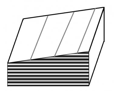
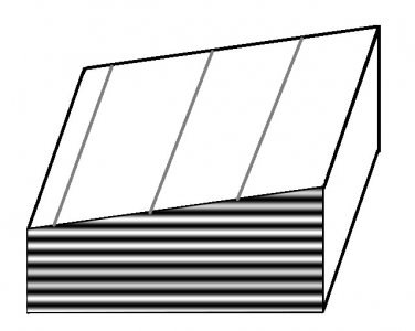
There is a tricky way to eliminate the higher/lower ambiguity. I used a variation of it to develop my own version of a deterministic polishing system for doing failure analysis on integrated circuits. Hopefully the two included figures and vigorous arm-waving on my part will explain it :)

Figure 2C.jpgFigure 2D.jpg
In both figures I'm showing the gap between a flat and the surface it's resting on. The light/dark horizontal bands show the locations of dark fringes in space. The vertical bands show the fringes that are created when the reflected light from the surface interferes with the light bouncing off the optical flat. Note the change in the positions of the fringes between the two figures. The difference is that the wavelength of light for the left-hand figure is slightly shorter than the right-hand side. It's not obvious unless you download these into a separate folder and then flip between them, but this shows that the fringes move FROM the widest gap when the wavelength decreases. Thus by slightly changing the wavelength of our light source the height vs depth ambiguity has been eliminated. However we STILL don't know the actual path length difference: but now we can refine the surface if we want to do so.

This seems to beg the question, "how can we slightly change the wavelength of our light source?". And the answer is to use your common LED's wavelength vs. temperature dependence. When a red LED gets hotter its bandgap decreases (see here for an explanation). So its wavelength increases. Conversely, its wavelength decreases as its temperature decreases. The best way to manage an LED in this fashion would be to use a thermoelectric cooler, with a purchased or home-made PID controller.

For a really nifty result you can make a series of photos taken with different LED temperatures and quickly page-flip through them to make a little movie of the fringes moving. In my case I wasn't changing the color of an LED (I was using a fixed-wavelength laser) but it so happens that silicon's index of refraction has a very strong temperature dependence. So by changing the temperature of the silicon I changed the effective path length, and the fringes moved as predicted.
 
Back
Top